Overview
The EBX-2054 is the EBX family's full-stack telematics box — a single unit that handles the cellular WAN, the GNSS positioning, the on-vehicle CAN reading, the in-cab WIFI hotspot, the E-Call / B-Call audio path and the 6-axis crash / harsh-event detection. It targets vehicles that need cellular connectivity for fleet management, OTA software update, remote diagnostics or driver-behaviour reporting — from a 12 V passenger-car connected-services build up to a 24 V heavy-truck fleet box, all on the same hardware platform thanks to the 10–32 VDC input range and the dual-rated 12 V / 24 V supply design.
The CPU is an ARM A7 running at 1.2 GHz with 2 Gbit RAM and 4 Gbit Flash — enough headroom to run an embedded Linux stack, the cellular modem driver, the GNSS receiver, the WIFI hotspot service and the customer telematics application concurrently without pushing the system. Reliability is dimensioned for the long-life automotive duty cycle: hardware Watchdog auto-recovery on software hang, environmental three-coat conformal-coating on the PCBA, a 320 mAh on-board RTC / service-runtime battery that keeps the telematics service alive ~10 min after external supply loss, and an expected service life ≥ 5 years.
Connectivity stack
Cellular WAN (4G LTE)
The EBX-2054 covers the full 4G LTE TDD / FDD compatibility set plus 3G WCDMA / TD-SCDMA fallback plus 2G GSM900 / GSM1800 fallback. SMS messaging is supported on the modem side. Dual-APN configuration lets the operator split the public-network traffic (e.g. driver-app web traffic) from the enterprise-network traffic (e.g. fleet-back-end telematics push) on the same SIM. The 4G antenna is external (FAKRA pigtail on the cellular antenna port) so the antenna can be roof-mounted away from the metal of the cab.
GNSS (GPS + BeiDou dual-system)
The integrated GNSS receiver supports GPS + BDS (BeiDou) dual-system positioning. Cold-start time-to-first-fix is < 40 s; warm-start is < 10 s. The position update rate is 1 Hz, with positioning accuracy < 10 m on the standard build. The GNSS antenna is the second FAKRA pigtail on the unit (typically a roof-mounted patch antenna).
In-cab WIFI 2.4 GHz hotspot
The EBX-2054 hosts a 2.4 GHz IEEE 802.11 b/g/n WIFI access-point, sharing the cellular WAN with up to 10 client devices at a theoretical peak of 150 Mbps on the radio interface. The WIFI antenna is built-in (no FAKRA pigtail needed for WIFI). The hotspot is intended as an in-cab amenity for the driver and passengers; the connected-services traffic uses the cellular WAN's dedicated APN.
E-Call / B-Call audio path
The EBX-2054 carries an on-board audio processing unit and an audio amplifier stage, so the unit can independently host the E-Call (emergency-call) and B-Call (business / call-centre) voice channels. Both manual and automatic call-centre dial-out are supported — an emergency button on the cab loom, or an automatic trigger from the 6-axis gyroscope's crash event, can put the operator into a voice call to the call-centre over the cellular WAN.
Engineering details
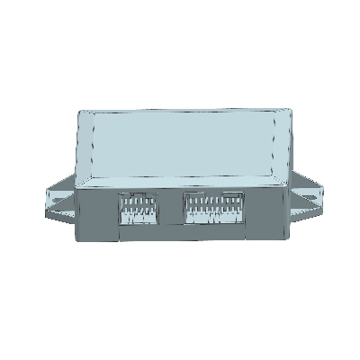
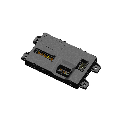
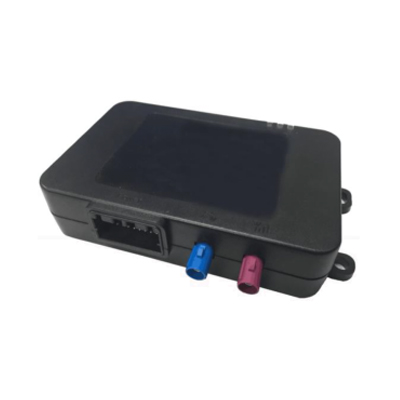
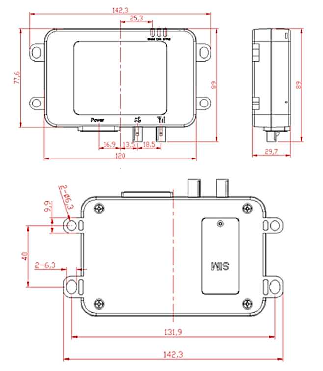
The EBX-2054 occupies a 142.3 × 89 mm footprint (120 mm body width × 77.6 mm depth, 142.3 mm over the four mounting ears) with a 32 mm overall height — the alternate build option drops the body down to < 123 × 81 × 32 mm. The harness interface is a single sealed 20-pin power / CAN / RS232 connector on one short edge, plus two FAKRA antenna pigtails (positioning + cellular, colour-coded blue + violet) and a SIM-card slot on the bottom face under a sealed cover.
- Industrial-grade single-chip MCU architecture — designed for the long-duty automotive cycle, not a consumer-electronics teardown
- Hardware Watchdog circuit — auto-resets and restarts the T-BOX on any software hang, so the fleet operator does not need a physical reset trip
- Three-coat conformal-coating on the PCBA — humidity, dust and salt-fog protection above the housing-level seal
- On-board 320 mAh RTC / service-runtime battery — RTC keeps time within ≤ 5 s drift over 24 h and holds time for up to 15 days after external supply loss; telematics service can stay alive ~10 min for tow-away / battery-pulled reporting
- Tight quiescent budget: ≤ 1 mA (CAN-wake / timer-wake), ≤ 2 mA (CAN / timer / G-sensor wake), ≤ 5 mA (active-sleep with remote-wake added); average working < 400 mA, peak < 600 mA
- External interfaces: UART × 2 (debug / customer port), CAN × 2 @ 250 kbps (1 with CAN-wake), ACC hard-wire input × 1 (ignition-on detection), LIN × 1 (reserved on the standard build)
- 3 status LEDs on the housing top — cellular link status / GNSS-lock status / CAN-bus health — visible for a fast field-service triage check without a laptop
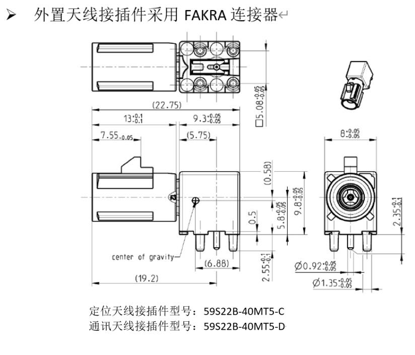
- FAKRA antenna interfaces — one positioning-antenna pigtail (blue body) and one cellular-antenna pigtail (violet body), per the SAE / USCAR FAKRA colour-coding
Mechanical layout
FAKRA antenna interface
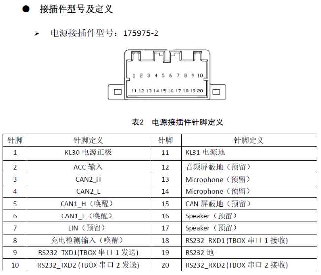
20-pin power / CAN / RS232 connector pin-out
The standard build lands all power, ground, CAN, ACC, LIN-reserved, audio-reserved and the RS232 customer ports on a single sealed 20-pin connector (reference housing P/N 175975-2). The reference pin-out below documents the channel allocation on the current production build; the customer harness drawing is the final specification at quotation.
| Pin | Function | Pin | Function |
|---|---|---|---|
| 1 | KL30 power + | 11 | KL31 power ground |
| 2 | ACC input | 12 | Audio shield ground (reserved) |
| 3 | CAN2 H | 13 | Microphone (reserved) |
| 4 | CAN2 L | 14 | Microphone (reserved) |
| 5 | CAN1 H (wake-up) | 15 | CAN shield ground (reserved) |
| 6 | CAN1 L (wake-up) | 16 | Speaker (reserved) |
| 7 | LIN (reserved) | 17 | Speaker (reserved) |
| 8 | Charge-detect input (wake-up) | 18 | RS232 RXD1 (T-BOX UART 1 RX) |
| 9 | RS232 TXD1 (T-BOX UART 1 TX) | 19 | RS232 ground |
| 10 | RS232 TXD2 (T-BOX UART 2 TX) | 20 | RS232 RXD2 (T-BOX UART 2 RX) |
Reliability & testability
The EBX-2054 carries the maintainability / testability / reliability discipline expected of a fleet-side T-BOX:
- Network diagnostics — built-in: communication / network-management / DTC reporting over the cellular WAN to the fleet back-end
- OTA software upgrade: customer telematics application + cellular modem firmware are both OTA-updatable from the back-end
- Self-test: on-board self-check covers PCBA rail voltages, critical-component temperatures and the main functional-block status; core software carries a self-test command set; key signals have dedicated test points on the PCBA
- Reliability spec: environmental / EMC / safety validation per the OEM programme profile; SRRC radio type approval (or the equivalent local-region radio type approval per the destination market); destination-market vehicle-side type approvals (e.g. CCC for the China market when the programme requires it) handled per project; IATF 16949 (formerly TS 16949) manufacturing system
- Service life: ≥ 5 years on the standard duty cycle
Comparison with other Youlai telematics / control modules
| Model | Pattern | WAN | GNSS | WIFI |
|---|---|---|---|---|
| EBX-2054 | Full-stack T-BOX | 4G LTE + 3G + GSM | GPS + BDS | 2.4 GHz hotspot (up to 10 clients) |
| EBX-2301 | Gateway only | — (routes K-Line to OBD) | — | — |
| EBX-2305 | BCM + integrated RF | — | — | — (no WIFI; RKE only) |
The EBX-2054 is the right choice for any program that needs cellular WAN + GNSS positioning + in-cab WIFI in a single ECU — whether for fleet telematics on a heavy truck, OTA software update on a connected passenger car, or driver-behaviour reporting on a bus / coach. For pure CAN routing (no cellular), look at EBX-2301; for body control without telematics, look at EBX-2305 or the wider BCM lineup.
Manufacturing & testing
Built under IATF 16949 (formerly TS 16949) with APQP project planning and a PPAP package available for OEM programmes. Every unit is end-of-line functional-tested before packaging — the 4G modem registration to a test cell, the GNSS satellite-lock acquisition, the WIFI access-point start-up, the audio path on both microphone and speaker reserved channels, the CAN1 / CAN2 communication, the RS232 customer ports, the ACC ignition-detect input, the 320 mAh RTC battery hold-up, the hardware Watchdog reset behaviour and the 3 status LEDs are all checked. Radio type approval (SRRC or local-region equivalent per destination market) is handled per programme.
How to ask
The EBX-2054 belongs to the Smart Control Modules family. To request the harness drawing, the cellular-band coverage map for your destination market, the GNSS / WIFI antenna pairing, the fleet-back-end protocol specification, the OTA-update toolchain or a PPAP package, please use the contact page with your target vehicle programme, expected annual volume and key technical requirements (destination market for cellular type-approval, cellular operator / SIM provider, fleet-back-end protocol, CAN baud, IP rating, connector preference). Drawings welcome.