Overview
The EBX-2301 is the EBX family's dedicated vehicle network gateway — the box that sits between the powertrain CAN, the body CAN, the chassis CAN, the new-energy high-voltage CAN, the infotainment CAN, the LIN sub-buses and the OBD K-Line diagnostic channel, and routes the right message onto the right segment at the right time. Six CAN channels, three LIN channels and one K-Line on one ECU is enough to cover a typical premium-passenger-vehicle network topology (powertrain + body + chassis + infotainment + new-energy + diagnostic), and the CAN-FD capability on CAN5 and CAN6 means the same hardware can host an OTA-update channel running at CAN-FD data rates without needing a different SKU.
Electrically the module operates on a 9–16 VDC main feed with quiescent current ≤ 1 mA — a gateway sits across the whole vehicle network and is almost always on the wake-up path, so the parking-current budget is dimensioned tight. The reserved switch / interrupt inputs (A16–A19 and B10–B11) give the integration team six unused signal pins to wire as wake-up sources, ignition inputs or service-mode triggers without needing a hardware change.
Engineering details
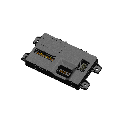
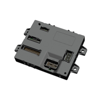
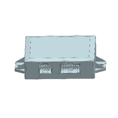
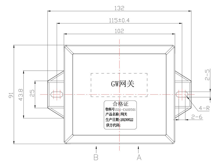
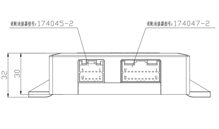
The EBX-2301 is a compact ECU with a 132 × 115 mm footprint (102 mm body width × 91 mm depth, 132 mm over the side mounting ears with two slotted M5 through-holes) and a ~32 mm overall height. The two harness connectors share the same edge of the housing (A-side and B-side side-by-side on the bottom face), so the harness designer can route the full 32-pin gateway loom in a single bundle. The shielded-pair allocation for the CAN segments uses the standard CAN_H / CAN_L / CAN_SHIL pattern, with the shield drain wired to chassis ground at the gateway end.
- Six CAN segments (CAN1–CAN6) with shielded-pair pin allocation on each segment — suitable for a premium-vehicle topology that splits powertrain / body / chassis / infotainment / new-energy onto separate buses
- Two CAN-FD-capable channels (CAN5, CAN6) — the same pin pair runs classical CAN on legacy architectures and CAN-FD on new-energy / OTA-update programs, no hardware change needed between the two configurations
- Three LIN sub-buses (LIN1, LIN2, LIN3) — covers the typical premium-vehicle LIN allocation (e.g. seat-control, door-modules, climate-control)
- K-Line diagnostic tunnel — OBD scan-tool side connects directly without needing a separate OBD-CAN adapter
- Compact 132 × 115 mm footprint with two side mounting ears (M5 slotted) — fits in the typical under-dash / behind-instrument-panel mounting envelope
- 32-pin single-edge harness: A-side 20-pin + B-side 12-pin Tyco sealed connectors on the same housing edge
- ≤ 1 mA quiescent — sized tight for an always-on gateway position on the wake-up path
- Six reserved switch / interrupt-line inputs on the standard build (A16–A19 + B10–B11) for the program to pin out as wake-up sources, ignition inputs or service-mode triggers
Mechanical layout
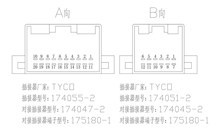
Harness connectors (reference table)
The standard build lands all 32 signal pins on two sealed Tyco connectors. The reference housing / terminal P/N below documents the current production build; the matching wire-side seals, terminals and per-pin allocation are confirmed against the customer harness drawing at quotation.
| Connector | Module-side housing | Wire-side housing | Terminal | Pins | Brand |
|---|---|---|---|---|---|
| A (20-pin) | 174055-2 | 174047-2 | 175180-1 | 20 | Tyco |
| B (12-pin) | 174051-2 | 174045-2 | 175180-1 | 12 | Tyco |
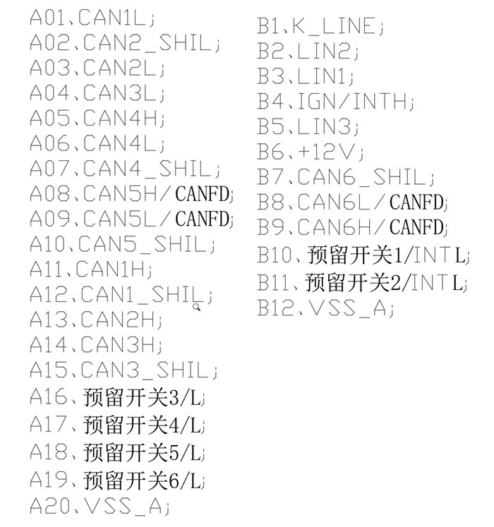
Pin-out — complete network map
The reference pin-out below documents the current production allocation across both connectors — six CAN segments, three LIN sub-buses, one K-Line diagnostic channel and the reserved switch / interrupt-input set. Final pin allocation is confirmed against the customer harness drawing at quotation.
| A-pin | Function | B-pin | Function |
|---|---|---|---|
| A01 | CAN1 L | B01 | K-Line (diagnostic) |
| A02 | CAN2 shield | B02 | LIN2 |
| A03 | CAN2 L | B03 | LIN1 |
| A04 | CAN3 L | B04 | IGN / interrupt-H |
| A05 | CAN4 H | B05 | LIN3 |
| A06 | CAN4 L | B06 | +12 V supply |
| A07 | CAN4 shield | B07 | CAN6 shield |
| A08 | CAN5 H / CAN-FD H | B08 | CAN6 L / CAN-FD L |
| A09 | CAN5 L / CAN-FD L | B09 | CAN6 H / CAN-FD H |
| A10 | CAN5 shield | B10 | Reserved switch 1 / interrupt-L |
| A11 | CAN1 H | B11 | Reserved switch 2 / interrupt-L |
| A12 | CAN1 shield | B12 | VSS_A (ground reference) |
| A13 | CAN2 H | B-side connector is 12-pin only | |
| A14 | CAN3 H | ||
| A15 | CAN3 shield | ||
| A16 | Reserved switch 3 / interrupt-L | ||
| A17 | Reserved switch 4 / interrupt-L | ||
| A18 | Reserved switch 5 / interrupt-L | ||
| A19 | Reserved switch 6 / interrupt-L | ||
| A20 | VSS_A (ground reference) | ||
Comparison with other Youlai network modules
| Model | Pattern | CAN segments | LIN | Diagnostic |
|---|---|---|---|---|
| EBX-2301 | Dedicated gateway | 6 (incl. 2 CAN-FD) | 3 | K-Line |
| EBX-2305 | BCM + integrated RF | Typical 1–2 (programme-specific) | 1–2 (programme-specific) | per BCM scope |
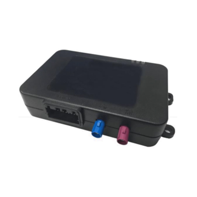
| EBX-2054 | T-BOX (telematics) | 2 + 4G WAN | 1 (reserved) | OTA over 4G |
The EBX-2301 is the right choice for any program that needs a dedicated routing gateway between multiple CAN segments and LIN sub-buses, particularly when the powertrain backbone has migrated to CAN-FD but the body / chassis side is still on classical CAN. The CAN-FD-capable channels (CAN5, CAN6) make it future-proof for an OTA-update bus added later in the programme life-cycle. For a BCM with a built-in CAN front-end (not a full gateway), look at EBX-2305; for telematics (4G LTE WAN + GNSS + CAN), look at EBX-2054.
Manufacturing & testing
Built under IATF 16949 with APQP project planning and a PPAP package available for OEM programmes. Every unit is end-of-line functional-tested before packaging — CAN bus health on all six segments, CAN-FD timing on CAN5 / CAN6, LIN1 / LIN2 / LIN3 sub-bus communication, the K-Line diagnostic loop-back, quiescent current under all wake-up profiles, and the reserved switch / interrupt-line inputs are all checked. Network-routing / filter-mask / gateway-DTC behaviour is loaded per the customer release.
How to ask
The EBX-2301 belongs to the Smart Control Modules family. To request the harness drawing, the network-routing specification, the CAN-FD timing profile or a PPAP package, please use the contact page with your target vehicle programme, expected annual volume and key technical requirements (CAN baud / CAN-FD data rate, LIN baud, diagnostic protocol, EMC profile, connector preference). Drawings welcome.