Overview — why a dedicated overload controller
Vehicle overload is one of the most heavily-regulated topics in the Chinese commercial-vehicle sector. Operating a heavy truck above its rated load damages the road, increases stopping distance, raises the risk of brake fade on long descents and shortens chassis life — with regulatory consequences that include on-the-spot fines, off-fleet impoundment and operator-licence sanctions. The regulation pushes the responsibility upstream onto the vehicle to continuously self-monitor the load state and warn the driver (and the back-end fleet system) when the rated load is exceeded.
The EBX-2209 addresses this requirement with a dedicated ECU that reads the suspension-height sensor pair at every wheel position, runs the calibrated suspension-deflection model in firmware to compute the per-axle and total-vehicle weight, and surfaces the result through three channels: the in-cab display (over the CAN-attached cluster), the in-cab audible warning, and the externally-visible warning channel (external horn + hazard-lamp flash). The unusually low ≤ 1 mA quiescent current means the controller can be permanently powered on the vehicle without measurable battery drain — important because the suspension-deflection baseline calibration needs to track temperature and parked-orientation drift over time.
Four integrated functions
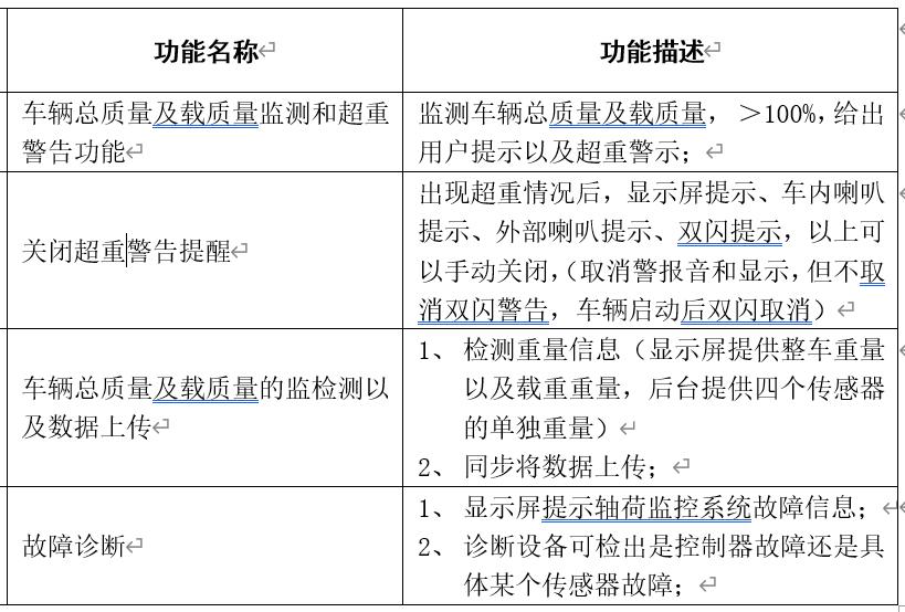
1. Vehicle gross + load weight monitoring with overload warning
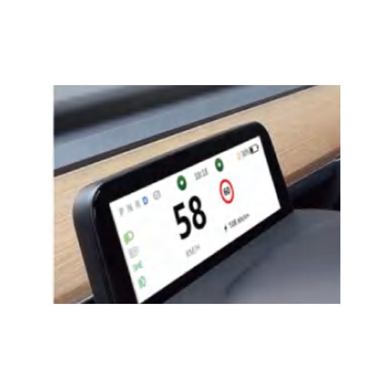
The controller continuously reads the four suspension-height sensor pairs, computes per-wheel weight using the calibrated suspension-deflection model, sums to per-axle and total weight, and compares the total against the programme-configured rated-load ceiling. When the load exceeds 100% of the rated load, the controller asserts the overload-state flag and routes the warning through all three channels simultaneously: the cluster display (showing the per-axle and total weight values plus the overload alert), the in-cab audible buzzer (typically via the cluster's buzzer driver), the external horn output and the body BCM's hazard-lamp flash.
2. Manual override of the audible warning — with hazard-lamp regulation-retention
The driver can manually mute the in-cab audible warning (cluster display + horn cancelled) once the overload state is acknowledged, but the hazard-lamp flash is regulation-retained until the vehicle is restarted — so the external indication of overload remains visible to enforcement / fleet observation even after the driver has muted the audible warning. The vehicle-restart event automatically cancels the hazard retention, returning the warning channel to the initial baseline on the next trip.
3. Data acquisition + CAN upload
The per-sensor weight reading (front-left / front-right / rear-left / rear-right), the per-axle weight reading (front axle + rear axle), the total vehicle weight and the rated-load percentage are all CAN-published to the cluster and the fleet back-end. The fleet back-end stores the load history per trip / per vehicle for fleet-level overload-trend analysis and per-driver behaviour reporting.
4. Fault diagnostic with per-sensor isolation
The plausibility-check across the dual-channel sensor pair (the two redundant readings from the same wheel position must agree within a tolerance band) gives the diagnostic logic per-sensor isolation: a fault on a single sensor channel surfaces as "sensor X faulty" rather than the generic "system fault", so the maintenance workshop can replace the specific failed sensor without trial-and-error. The controller publishes the per-sensor fault state over CAN to the cluster and to the OBD-style diagnostic tool.
Sensor architecture
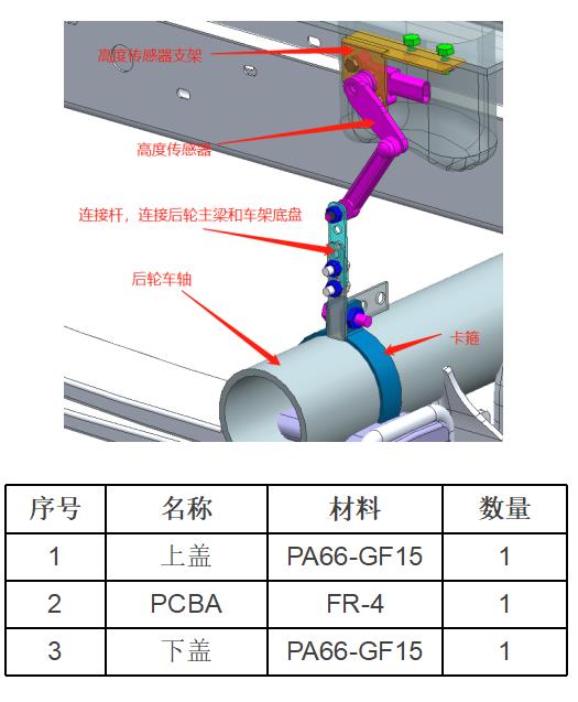
Suspension-mounted displacement sensor (sold separately)
The EBX-2209 works with a 4-pack of suspension-height (displacement / rotary-position) sensors. Each sensor is mounted between the rear-wheel axle and the chassis frame through a sensor bracket and a linkage rod — with the rotary axis of the sensor at the upper end on the bracket and the lower end of the linkage rod attached to the axle via a clamp. As the suspension compresses under load, the linkage rod rotates the sensor's shaft, and the sensor outputs a per-channel position reading (dual-channel for redundancy). The reading scales linearly with suspension deflection, which scales (per the calibrated suspension-deflection model) with the weight on that wheel position.
A typical 4×2 freight hauler installation uses 4 sensors (one per wheel position); a 6×4 tractor uses 6 sensors (two extra for the second rear axle); a tractor-trailer combination uses additional sensors on the trailer-side axles. The EBX-2209 firmware is configured at quotation for the target axle configuration.
Engineering details
- Per-channel dual-redundant sensor reading — each wheel position has two independent sensor channels into the controller, with a firmware-side plausibility-check across the pair; gives per-sensor fault isolation rather than the generic "system fault"
- Calibrated suspension-deflection model — the firmware carries a per-vehicle calibration table that maps the suspension-position reading to the per-wheel weight; the calibration is loaded at programme commissioning and tracked over time against the parked-baseline drift
- Three-channel warning — cluster display, in-cab audible warning, external horn + hazard-lamp flash — covers driver-facing, enforcement-facing and fleet-facing indication on a single warning event
- Regulation-retained hazard-lamp flash on overload, with vehicle-restart auto-cancel — the policy is regulation-aware: the driver can mute the in-cab nuisance noise after the warning is acknowledged, but the externally-visible warning channel is preserved through the rest of the trip
- ≤ 1 mA quiescent current — one of the lowest quiescent currents in the EBX family; suitable for always-on installation on the vehicle without measurable battery drain over a long parked period
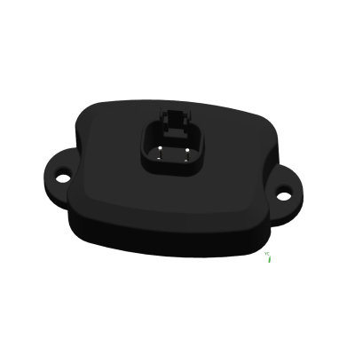
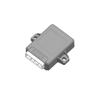
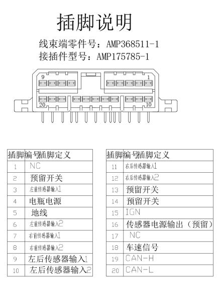
- Single 20-pin AMP 368511-1 connector — one harness mating, one harness routing; the matching wire-side housing is AMP 175785-1 with industry-wide availability
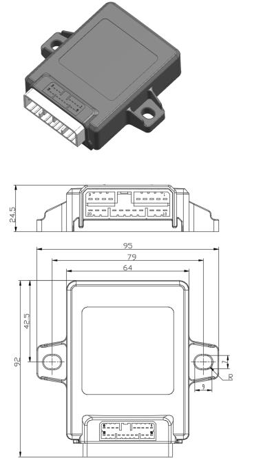
- Compact 95 × 92 × 24.5 mm body — takes a small footprint on the cab-side or chassis-side bracket between the cab and the loading area
- Free-orientation mounting; IP53 sealing class for in-cab / under-cab placement (specify a sealed-connector variant at quotation for under-chassis IP65 / IP67 placement)
Mechanical layout
20-pin pin-out reference
The standard build lands all signals on the single 20-pin AMP connector per the reference pin-out below. Final pin allocation is confirmed against the customer harness drawing at quotation.
| Pin | Function | Pin | Function |
|---|---|---|---|
| 1 | NC | 11 | Rear-right sensor input 1 |
| 2 | Reserved switch input | 12 | Rear-right sensor input 2 |
| 3 | Front-left sensor input 1 | 13 | Reserved switch input |
| 4 | Battery supply | 14 | Reserved switch input |
| 5 | Ground | 15 | IGN |
| 6 | Front-left sensor input 2 | 16 | Sensor power output (reserved) |
| 7 | Front-right sensor input 1 | 17 | NC |
| 8 | Rear-left sensor input 1 | 18 | Vehicle-speed input |
| 9 | Rear-left sensor input 2 | 19 | CAN-H |
| 10 | Front-right sensor input 2 | 20 | CAN-L |
Function configuration reference
Comparison with other Youlai specialised controllers
| Model | Function | Sensor count | Application |
|---|---|---|---|
| EBX-2209 | Axle-load / overload monitor | 4 wheel positions × 2 channels = 8 inputs | Chinese overload regulation compliance |
| EBX-957 | TPMS receiver (tyre pressure) | RF receiver (1 per vehicle), 4–18 wheel sensors via RF | Tyre-pressure monitoring |
| EBX-963 | Dump-truck body controller | 2-channel load-cell weighing (as a subset) | Dump-truck body automation + bed weighing |
The EBX-2209 is the right choice for a 24 V heavy-truck / freight-hauler programme that needs a dedicated overload-monitoring ECU for the Chinese commercial-vehicle overload regulation, with the warning channels (display + horn + external horn + hazard-lamp) properly orchestrated. For tyre-pressure monitoring (a related but separate fleet-management feature), see the EBX-957 TPMS receiver; for a dump-truck programme where load-cell-based bed weighing is part of a larger body-side controller scope, see the EBX-963 dump-truck body controller.
Manufacturing & testing
Built under IATF 16949 with APQP project planning and a PPAP package available for OEM programmes. Every unit is end-of-line functional-tested before packaging — the 4 dual-channel sensor inputs across the full input range, the calibration-table load via CAN, the per-sensor plausibility-check across the dual-channel pair, the overload threshold trip + horn output + hazard-lamp output, the manual-override input with the regulation-retained hazard-lamp policy, the IGN-gated wake-up, the ≤ 1 mA quiescent measurement and the CAN bus health are all checked.
How to ask
The EBX-2209 belongs to the Smart Control Modules family. To request the harness drawing, the suspension-height sensor specification, the calibration-table loading toolchain, the per-axle configuration option (4×2 / 6×4 / tractor-trailer), the CAN message catalogue or a PPAP package, please use the contact page with your target vehicle programme, expected annual volume and key technical requirements (axle configuration, rated load + per-axle ceiling, suspension type + deflection range, fleet back-end data protocol, CAN baud, IP rating, connector preference). Drawings welcome.