Overview
The EBX-963 is the EBX family's dedicated dump-truck / tipper body-side controller — the ECU that runs the four function groups specific to the dump-truck programme that a general-purpose BCM does not cover: top-cover automation (the rolling / sliding bed cover that closes during haul and opens during loading / tipping), tail-gate automation (the rear gate that opens to let the load discharge during tipping), lift / PTO automation (the hydraulic-lift solenoid that raises the bed plus the power-take-off solenoid that engages the hydraulic pump), and 2-channel load-cell weighing (the C6 + C8 analog channels from the bed-mounted load cells, summed and CAN-published as the live bed load).
The controller is validated against the customer's construction-machinery EMC specification, aligned with the de-facto reference profile used across the Chinese construction-machinery sector; programme-specific EMC compliance scope (test items, severity levels, observation criteria) is confirmed against the customer's own EMC matrix at quotation. The 433 MHz RF receive path supports the supplied 2-button remote key, so the driver can operate the top-cover or the tail-gate from beside the vehicle during the tipping operation without needing to be in the cab; a configurable APP-side remote-control path lets a fleet back-end command the same functions over the programme's telematics box (typical pairing: the EBX-2054 T-BOX upstream).
Function group walk-through
1. Top-cover open / close / position-limit chain
Three dedicated solenoid drive channels and three position-limit switch inputs run the top-cover automation:
- A2 — top-cover open solenoid drive (high-side relay drive into the open-direction valve)
- A3 — top-cover close solenoid drive (high-side relay drive into the close-direction valve)
- A1 — lift-and-control horizontal switching solenoid drive (the directional-control valve that selects between the top-cover hydraulics and the lift hydraulics on a shared hydraulic circuit)
- A18 / A19 / A20 — top-cover position-limit switches — S1 (home), S3 (raised-limit), S2 (closed-limit) inputs that close the position-closed-loop; the controller stops the corresponding drive on limit-reached
- A15 / A16 — top-cover open switch input + close power input — driver-side or remote-side commanded open / close request
- B9 — reserved top-cover input 4 for programme-specific extension (e.g. partial-open mode)
2. Tail-gate automation (left + right + air-blow)
- A7 / A8 — tail-gate left / right open output (independent drives so the gate can open straight or unbalanced if the load is uneven)
- A5 — tail-gate air-blow solenoid drive (the air-blow valve that ejects residual material from the gate seam after the gate opens)
- B6 / B7 — tail-gate left / right switch inputs
3. Lift / PTO sub-system
- A6 — lift solenoid drive (the lift-direction valve that raises the bed)
- A4 — switching-type PTO solenoid drive (the power-take-off engagement valve that engages the hydraulic pump from the transmission take-off)
- A17 — PTO switch input (the in-cab PTO engagement switch — safety-interlock-gated)
4. 2-channel load-cell weighing
- B1 / B2 — load-cell C6 / C8 analog input (the two analog channels from the bed-mounted load-cell pair); the controller pre-processes the analog readings and publishes the live bed-load on CAN for the cluster / fleet back-end
5. Safety / emergency / zone-specific inputs
- B3 — emergency switch input (cut-out for the entire body-side hydraulic sub-system)
- B4 — zone-specific switch input (geofence / zone-permission switch — the body-side automation can be disabled when the vehicle is outside a permitted operating zone)
- B5 — pressure switch input (hydraulic-pressure threshold detection — cuts the lift drive if the hydraulic pressure exceeds the safe ceiling)
- B8 — reserved switch input 4 for programme-specific safety chain extension
6. Network & remote-control
- B11 / B12 — CAN-L / CAN-H — programme-defined message catalogue (CAN protocol confirmed per program; J1939 family typical for 24 V construction-machinery programmes)
- 433 MHz RF receive path — supports the supplied 2-button remote key (open / close); the controller's RF receiver demodulates the ASK-modulated burst and the firmware pairs against the learned key ID
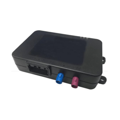
- APP-side remote-control — fleet-back-end commands route over the programme's telematics box (typical pairing: the EBX-2054 T-BOX upstream) onto CAN, and the EBX-963 subscribes to the command messages
Engineering details
- Four-fold safety protection on each high-current drive channel — particularly important on the solenoid-valve drive channels where a stuck-valve is the routine fault mode and the protection envelope keeps a single-valve fault from taking out the rest of the body-side automation
- Drive-channel mix: 3 × high-side relay-coil drive + 1 × low-side relay-coil drive + 2 × chip-level high-side drive — lets the programme allocate the relay-side drive to the higher-current solenoid valves (lift, top-cover) and the chip-level drive to the lower-current accessory loads
- 15 × digital switch inputs + 2 × analog inputs — covers the full body-side switch / sensor inventory of a typical dump-truck programme on a single ECU
- 433 MHz RF receive path with learn-mode pairing — the programme can pair a new remote key without an external tool, per the programme's key-management policy
- APP-side remote-control over CAN — via the programme's telematics box; the EBX-963 has no direct cellular WAN on board (intentional, to keep the controller in the body-side safety scope rather than in the connectivity scope)
- Construction-machinery OEM EMC compliance — the controller has been validated against the customer's EMC specification, aligned with the de-facto reference profile used across the Chinese construction-machinery sector; programme-specific scope confirmed at quotation
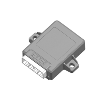
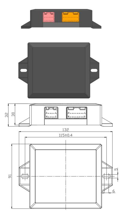
- Free-orientation mounting; compact 132 × 91 × 32 mm body for a sheltered chassis-side bracket near the hydraulic-valve manifold — the IP53 housing wants a position shielded from direct wash-down / road-spray, so specify a sealed-connector variant at quotation if the bracket is exposed
Mechanical layout
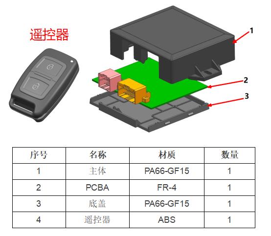
Construction (PA66-GF15 + FR-4 PCBA + 2-button remote key)
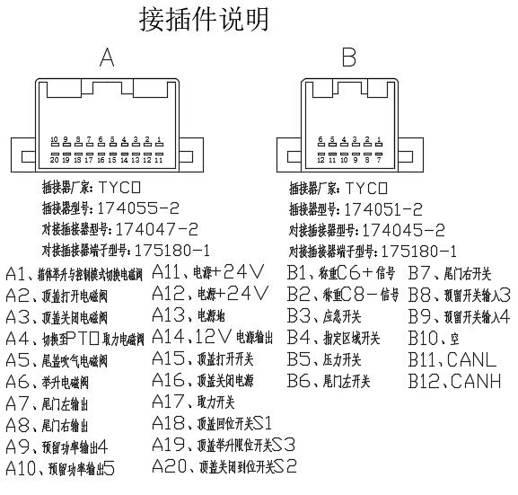
32-pin pin-out reference (connector A + connector B)
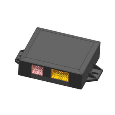
The standard build lands all signals across the two sealed TYCO connectors per the reference pin-out below. Final pin allocation is confirmed against the customer harness drawing at quotation.
| Pin | Connector A — 20-pin TYCO 174055-2 (drive + power side) | Pin | Connector B — 12-pin TYCO 174051-2 (input + CAN side) |
|---|---|---|---|
| A1 | Lift-and-control horizontal switching solenoid drive | B1 | Load-cell C6+ signal (analog) |
| A2 | Top-cover open solenoid drive | B2 | Load-cell C8+ signal (analog) |
| A3 | Top-cover close solenoid drive | B3 | Emergency switch input |
| A4 | Switching-type PTO solenoid drive | B4 | Zone-specific switch input |
| A5 | Tail-gate air-blow solenoid drive | B5 | Pressure switch input |
| A6 | Lift solenoid drive | B6 | Tail-gate left switch input |
| A7 | Tail-gate left open output | B7 | Tail-gate right switch input |
| A8 | Tail-gate right open output | B8 | Reserved switch input 4 |
| A9 | Reserved power output 4 | B9 | Reserved top-cover input 4 |
| A10 | Reserved power output 5 | B10 | (unused) |
| A11 | Power +24 V | B11 | CAN-L |
| A12 | Power +24 V | B12 | CAN-H |
| A13 | Power ground | (12-pin connector B ends at row B12) | |
| A14 | +12 V auxiliary output | ||
| A15 | Top-cover open switch input | ||
| A16 | Top-cover close power input | ||
| A17 | PTO switch input | ||
| A18 | Top-cover home-position switch S1 | ||
| A19 | Top-cover raised-limit switch S3 | ||
| A20 | Top-cover closed-limit switch S2 | ||
Comparison with other Youlai construction-machinery modules
| Model | Function scope | Remote | Application |
|---|---|---|---|
| EBX-963 | Top-cover + tail-gate + lift + PTO + 2-ch weighing | 433 MHz RF key + APP via T-BOX | Dump truck / tipper / mining vehicle |
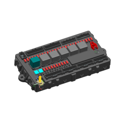
| EBX-952 | Full-scope 24 V BCM (general purpose) | RKE / App remote | Heavy truck (general) |
| EBX-2510 | 24 V BCM with configurable analog inputs | None (CAN only) | Specialised analog-rich applications |
The EBX-963 is the right choice for a dedicated dump-truck / tipper programme that wants one ECU to own the body-side automation (top-cover, tail-gate, lift, PTO, weighing) plus driver-out-of-cab remote control over both the 433 MHz RF key and the fleet-back-end APP. For a general-purpose 24 V BCM, look at EBX-952; for a configurable analog-input-rich BCM that can absorb a custom sensor pack, look at EBX-2510.
Manufacturing & testing
Built under IATF 16949 with APQP project planning and a PPAP package available for OEM programmes. Every unit is end-of-line functional-tested before packaging — the 3 + 1 + 2 = 6 drive channels (each across full-on / full-off / current-limit trip), the 15 digital switch inputs, the 2 analog load-cell inputs across the full input range, the 433 MHz RF receive path with a paired test key, the +12 V auxiliary output rail, the CAN bus health and the four-fold safety-protection envelope (over-voltage / over-current / short-circuit / over-temperature trip and recovery) are all checked. EMC validation per the customer's construction-machinery EMC specification is performed in our in-house lab.
How to ask
The EBX-963 belongs to the Smart Control Modules family. To request the harness drawing, the hydraulic-valve manifold mating documentation, the RF remote-key pairing toolchain, the APP-side remote-control message profile, the CAN message catalogue or a PPAP package, please use the contact page with your target vehicle programme, expected annual volume and key technical requirements (top-cover style, tail-gate configuration, lift hydraulic specification, load-cell model, CAN protocol, IP rating, connector preference). Drawings welcome.