Overview
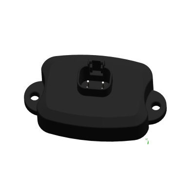
The EBX-953 is a 24 V body control module engineered for heavy-truck, bus / coach, construction-machinery and commercial-vehicle platforms that need both a body-control logic core and the downstream fuse / relay carrier in one sealed unit. Where a typical BCM stops at logic-level outputs and hands current routing back to an external power distribution box, the EBX-953 integrates the relay drivers, the 24-volt main relays and a 37-position mini-blade fuse bank onto the same PCBA assembly. The result is one ECU on the harness instead of one BCM plus one PDB — fewer connectors, less inter-box wiring, simpler diagnostics.
Electrically the module operates across an 18–32 VDC range with quiescent current ≤ 5 mA. Four-layer hardware protection (over-voltage / over-current / short-circuit / over-temperature) covers each output channel. The communication backbone is three CAN buses (a PCAN powertrain / chassis bus, an ICAN inter-controller bus and a dedicated upper-vehicle CAN for body-builder / aftermarket integration) plus one LIN bus typically allocated to the electric-window sub-network.
Integrated functions
The EBX-953 consolidates the body-control functions that a heavy commercial vehicle typically spreads across a BCM plus several discrete controllers:
- Ignition & power management. ON-fire control and ECU ON-fire control, ACC control, ignition-lock control, electrical power management for downstream subsystems.
- Lighting. Headlamp / position lamp / fog lamp / turn signal / brake lamp / reverse lamp drive and feedback, plus body-builder reserved channels.
- Wiper & HVAC. Front and rear wiper drive (intermittent / low / high), washer pumps, fan control, HVAC compressor / blower interlocks, pre-heat control.
- Central locking & electric windows. Door lock / unlock drive, horn drive, 4-door electric window up / down outputs with reserved positions for rear-right and rear-left windows.
- Drivetrain & aftermarket. Gear-position monitoring, radio / cluster interlocks, engine fault feedback, seat-belt warning, sensor signal acquisition (analog + frequency).
- Vehicle network. Three CAN buses (PCAN / ICAN / upper-vehicle CAN) for inter-controller communication and body-builder integration; one LIN bus typically dedicated to electric-window sub-network communication.
Engineering details
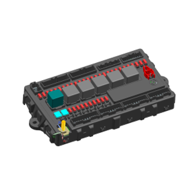
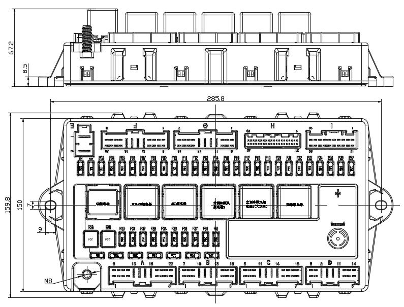
The EBX-953 occupies a 285.8 × 159.8 mm footprint with a 67.2 mm overall height (including connector profiles), an M8 stud at each of the four corners and a PA + PPO upper / lower housing with an aluminium heat-spreader plate above the PCBA. The internal carrier holds 5 main relays (ON relay, alternator-excitation relay, ACC relay, whole-vehicle central-signal relay, upper-vehicle / body-builder power relay), ~37 mini-blade fuses on the central bus, plus slow-blow main-feed fuses on the high-current branches.
- Four-layer per-output protection — over-voltage cut-off, over-current limiting, short-circuit isolation and over-temperature de-rating — covering both the logic-side drivers and the integrated fuse/relay carrier outputs
- 3 CAN buses (PCAN powertrain / chassis · ICAN inter-controller · upper-vehicle CAN body-builder) — protocol confirmed per program (J1939 family commonly used on commercial-vehicle networks)
- 1 LIN bus — typically allocated to the electric-window sub-network on the standard build; alternative allocations available per program
- I/O density: 11 power/ground hard inputs, 46 digital inputs, 9 analog inputs, 2 pulse/frequency inputs against 43 high-side + 3 low-side outputs and 48 fuse/relay-protected power outputs — one of the higher I/O densities in the EBX BCM range
- IP53 sealing (dust-protected, splash-protected) suitable for cab-mounted installation; specify a sealed-connector variant at quotation if the program requires chassis-mounted IP67
Mechanical layout & internal carrier
Mating connectors
Current-production EBX-953 housings include 9 OEM-grade automotive connectors from Tyco/AMP and KET. The reference P/N below documents the connectors on the current production build; the matching wire-side seals, terminal P/N and harness colour code are confirmed against the customer harness drawing at quotation.
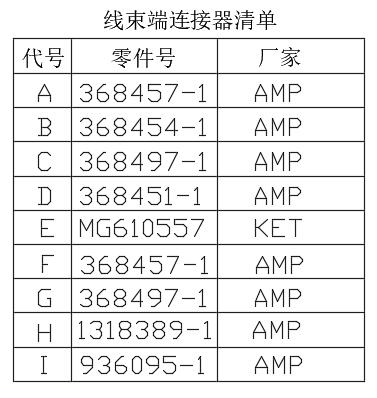
| ID | Reference P/N | Brand |
|---|---|---|
| A | 368457-1 | Tyco/AMP |
| B | 368454-1 | Tyco/AMP |
| C | 368497-1 | Tyco/AMP |
| D | 368451-1 | Tyco/AMP |
| E | MG610557 | KET |
| F | 368457-1 | Tyco/AMP |
| G | 368497-1 | Tyco/AMP |
| H | 1318389-1 | Tyco/AMP |
| I | 936095-1 | Tyco/AMP |
Construction & bill of materials
| # | Component | Reference material / family | Qty |
|---|---|---|---|
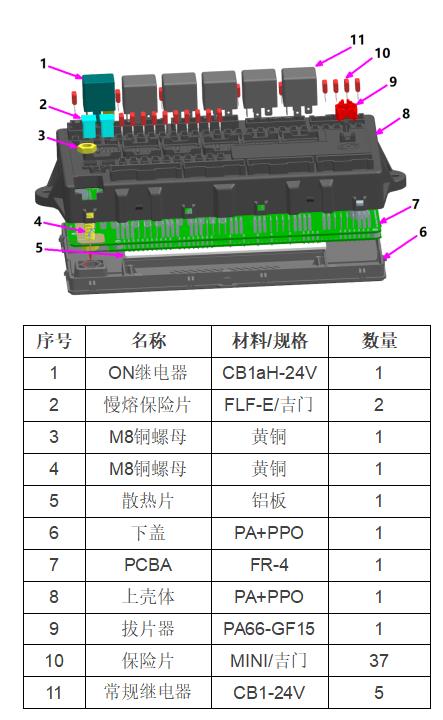
| 1 | ON relay | ISO sealed mini-relay (24 V coil; reference CB1aH-24V or equivalent) | 1 |
| 2 | Slow-blow fuse | FLF-E family slow-blow bolt-down (Jimen-style or equivalent) | 2 |
| 3 | M8 stud | Brass | 1 |
| 4 | M8 stud | Brass | 1 |
| 5 | Heat-spreader plate | Aluminium | 1 |
| 6 | Lower housing | PA + PPO | 1 |
| 7 | PCBA | FR-4 | 1 |
| 8 | Upper housing | PA + PPO | 1 |
| 9 | Fuse extractor | PA66-GF15 | 1 |
| 10 | Mini-blade fuses | MINI-blade family (Jimen-style or equivalent) | 37 |
| 11 | Standard relays | ISO sealed mini-relay (24 V coil; reference CB1-24V or equivalent) | 5 |
Comparison with other Youlai BCM modules
The EBX-953 is the 24 V integrated-carrier member of the BCM range. The table below sets it against the pure-logic siblings and the 12 V class, so a programme can land on the right voltage and the right architecture — one-box (logic + fuse/relay) or logic-only with a separate distribution box:
| Model | System | Pattern | I/O density | Footprint |
|---|---|---|---|---|
| EBX-953 | 24 V (18–32 VDC) | Integrated fuse/relay BCM | ~110 I/O + 48 protected outputs | 285.8 × 159.8 mm |
| EBX-2305 | 12 V (9–16 VDC) | Pure-logic BCM + integrated RF | ~120 I/O across J1/J2/J3 | Compact, new-energy class |
| EBX-2313 | Light truck class | Pure-logic BCM (no integrated fuse/relay) | ~100 I/O across 5 connectors | 138 × 170 mm |
| EBX-954 | 24 V (18–32 VDC) | Pure-logic BCM + RKE-ready | 67 in · 45 out | 193.6 × 157.8 mm |
The EBX-953 is the right choice when a 24 V program wants one box on the harness instead of a separate BCM plus PDB. For a 24 V program that keeps the BCM logic pure and routes fuse / relay through a separate NBX box, the EBX-954 is the closer match. For a 12 V new-energy program with RKE / PKE smart-key requirements, the EBX-2305 is the closer match. For a light-truck BCM with pure logic and no integrated fuse/relay (12 V or 24 V per programme), the EBX-2313 is the right tier.
Manufacturing & testing
Built under IATF 16949 with APQP project planning and a PPAP package available for OEM programmes. Every unit is end-of-line functional-tested before packaging — CAN/LIN bus health, current draw, the lighting / locking / window / wiper I/O matrix and each integrated fuse / relay position are all checked. Environmental validation and EMC pre-compliance screening in our in-house lab is run when the programme requires it.
How to ask
The EBX-953 belongs to the Smart Control Modules family. To request the harness drawing, the per-position fuse / relay map or a PPAP package, please use the contact page with your target vehicle programme, expected annual volume and key technical requirements (target voltage class, CAN protocol family, IP rating, working temperature, connector preference). Drawings welcome.