Overview — the auxiliary-bus power hub on a new-energy commercial vehicle
An electric heavy truck or electric bus carries one big 24 V auxiliary bus that supplies every low-voltage ECU on the vehicle — lighting, BCM, instrument cluster, all the sensor / actuator electronics, cabin HVAC blowers, the steering-assist controller, the cabin radio. On an internal-combustion vehicle that bus is supplied by an alternator running off the engine; on an electric vehicle there is no alternator, and the bus has to be supplied by a DC-DC converter that pulls energy down from the high-voltage traction pack. Sizing matters: a fully-loaded heavy truck with high-power lighting, working-light banks, blower motors and a multi-display cabin can easily pull 20-30 kW on the 24 V bus at peak.
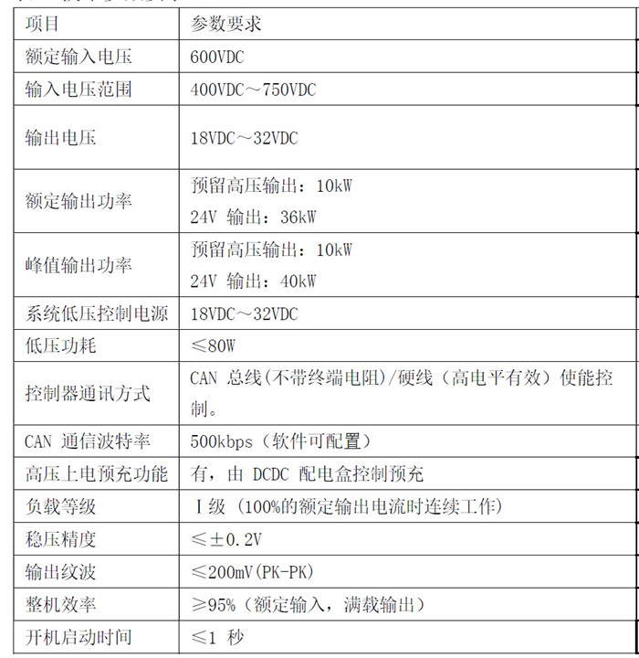
The EBX-2314 is the controller for that DCDC role on a heavy-duty new-energy commercial vehicle. The 600 VDC nominal high-voltage input (400-750 VDC operating range) covers the typical traction-pack nominal voltage classes used on Chinese heavy-truck and bus programmes; the 18-32 VDC output covers the 24 V auxiliary bus from cold-crank-low to high-charge ceiling; the 36 kW rated / 40 kW peak output sizing gives the auxiliary bus a comfortable headroom on top of the typical peak load. The separate 10 kW reserved high-voltage output channel handles HV-side accessory loads (HV-side heater elements, HV-side compressor drives) without adding a second control box.
The headline efficiency number is ≥ 95 % at full load, which on a 36 kW rated output represents ≤ 1.9 kW of conversion loss — meaningful both for the auxiliary-bus thermal-management story and for the range / efficiency margin of the overall vehicle. Tight regulation (≤ ± 0.2 V) keeps the 24 V bus inside the comfortable supply window for every downstream ECU; low output ripple (≤ 200 mV PK-PK) keeps the audio / sensor sub-systems clean.
Engineering details
On-board high-voltage pre-charge control
On a high-voltage traction system, closing the main contactor onto a cold DC bus without a pre-charge stage would draw an enormous in-rush current into the link capacitance of every downstream HV consumer (drive inverter, DCDC, HV compressor, HV heater) — large enough to weld the contactor or burst the link capacitor in extreme cases. The standard solution is a pre-charge resistor in series with the bus, gated by a smaller pre-charge contactor, that lets the bus voltage rise gradually until it has converged to within tolerance of the pack voltage; only then is the main contactor closed and the pre-charge contactor opened.
The EBX-2314 owns the pre-charge sequence: the controller drives the pre-charge enable, monitors the bus voltage rise against the configured convergence window, and signals the BMS to close the main contactor when the pre-charge has converged. Bundling the pre-charge into the DCDC controller removes the separate pre-charge box typical of older designs and reduces the inter-ECU CAN handshake count.
CAN + hard-wire enable
The controller speaks 2 × CAN at 500 kbps — one bus for normal data communications (status, fault, regulation set-point), one bus for calibration / firmware download. Both buses are software-configurable up to a CAN-FD upgrade path when the programme moves to a faster vehicle-network spec. In addition, a high-level hard-wire enable line serves as the backup enable path — the DCDC can be enabled even when the CAN bus is unavailable, which is critical during fault-recovery scenarios where the bus may be down.
UDS + J1939-73 DM1 diagnostics
Full UDS (ISO 14229) on-line diagnostics is supported — the controller responds to the standard UDS read-DTC, clear-DTC and read-data-by-identifier services from any UDS-compliant diagnostic tool. J1939-73 DM1 active-fault dispatch keeps the fleet-side telematics tool (any J1939-compliant scanner) informed of the controller's active-fault list in real-time without polling.
Protection envelope
The protection state machine catches four classes of fault on every drive channel:
- Short-circuit — immediate disconnect, fault flag asserted, self-reset attempt after a configured cool-down
- Reverse-polarity — blocking diode on the HV-input side prevents driver-stage damage from a reversed harness during installation
- Long-term overload — the channel tolerates short over-rating bursts but trips when the I×t integral exceeds the configured threshold
- Over-temperature — thermistor-monitored junction temperature trips at the programmed threshold and re-enables on cool-down
Every fault asserts the per-fault diagnostic flag on both the UDS DTC catalogue and the J1939-73 DM1 message, so the fleet-side scanner and the workshop UDS tool see the same fault list.
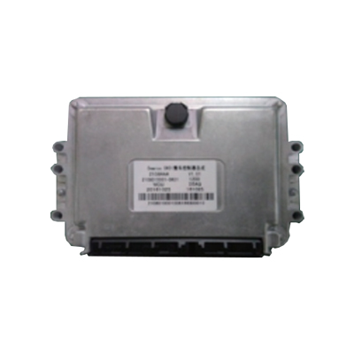
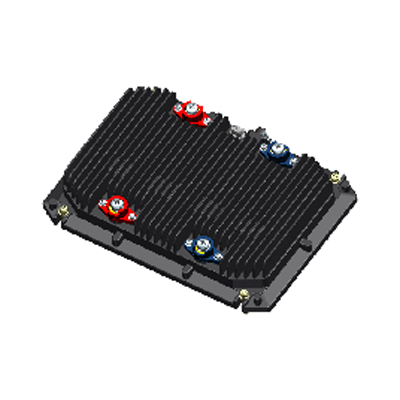
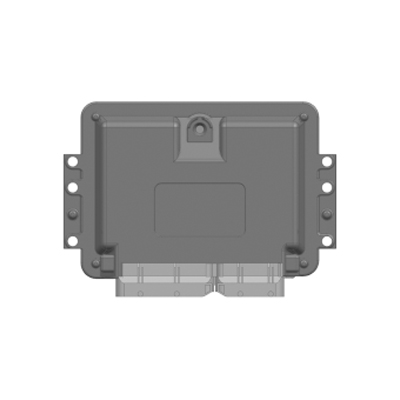
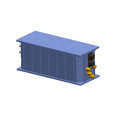
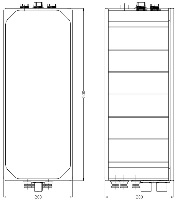
Mechanical layout
Full technical reference
Comparison with the related Youlai power modules
| Model | Input → Output | Output power | Efficiency | Pre-charge? |
|---|---|---|---|---|
| EBX-2314 | 600 VDC (400-750) → 18-32 VDC (24 V) | 36 kW rated / 40 kW peak | ≥ 95 % | Yes (on-board) |
| EBX-2407 | 24 V → 12 V step-down + dual-battery equaliser | 100 A / 30 A two SKUs | n/a | n/a |
| EBX-960B | VBU (VCU + BMS algorithm fusion) | n/a | n/a | n/a |
The EBX-2314 is the right choice for the main HV→24V auxiliary DCDC role on a heavy-duty new-energy commercial vehicle. For a programme that wants the auxiliary 24V to 12V step-down + dual-battery equaliser combo, look at EBX-2407; for the upstream powertrain-domain controller that issues the DCDC enable command, look at EBX-960B VBU.
Manufacturing & testing
Built under IATF 16949 with APQP project planning and a PPAP package available for OEM programmes. Every unit is end-of-line functional-tested before packaging — the HV-input voltage range across the 400-750 VDC envelope (cold-start, mid-range, top-range), the 24V output regulation under full 36 kW continuous load with rise-time measurement (≤ 1 s start-up), the output ripple measurement (≤ 200 mV PK-PK), the regulation accuracy measurement (≤ ± 0.2 V), the full-load efficiency measurement (≥ 95 %), the HV pre-charge sequence (enable / monitor / converge / signal BMS), the protection state machine on each fault class (short-circuit / reverse-polarity / long-term overload / over-temperature), the UDS responses on the standard service set, the J1939-73 DM1 fault dispatch, and the dual-CAN bus health are all checked.
How to ask
The EBX-2314 belongs to the Smart Control Modules family. To request the harness drawing, the HV-input extended-range option (above 750 VDC), the HV connector option matrix, the LV connector option matrix, the pre-charge convergence window tuning, the UDS DTC catalogue, the J1939-73 DM1 SPN list or a PPAP package, please use the contact page with your target vehicle programme, traction-pack nominal voltage and operating range, expected annual volume and key technical requirements (24V auxiliary peak load, HV-side accessory load list, pre-charge contactor topology, FOTA scope, EMC profile, IP rating). Drawings welcome.