Overview — from two ECUs to one domain controller
A first-generation new-energy vehicle architecture splits the powertrain-side intelligence into two separate ECUs: a VCU (Vehicle Control Unit) on the chassis side runs the torque-request strategy, the drive-mode logic and the energy-management loop; a BMS (Battery Management System) on the pack side runs the cell-balancing algorithm, the SOC / SOH estimator and the contactor-control state machine. The two ECUs exchange dozens of CAN messages per cycle — pack voltage, pack current, cell-temperature map, individual cell-voltage map, SOC estimate, SOH estimate, BMS fault state, BMS contactor state, VCU torque request, VCU drive-mode request, VCU power-limit acknowledge — and the timing of those messages becomes part of the safety-relevant control loop.
The two-box pattern is simple to design but it has hidden costs: two ECUs to validate, two housings to seal, two connector faces in the harness, two suppliers to qualify in some programmes, and the inter-box CAN traffic that occupies a non-trivial fraction of the vehicle-CAN bus bandwidth. On a vehicle that already runs a CAN-FD bus near 60-70 % nominal load (typical for a mid-range new-energy passenger car or a heavy-duty electric truck with a rich peripheral set), the VCU↔BMS exchange alone can be the difference between a healthy bus and a bus that starts dropping messages under transient bursts. For how the VCU compares with the BCM and PMU across the wider architecture, see the BCM vs VCU vs PMU comparison.
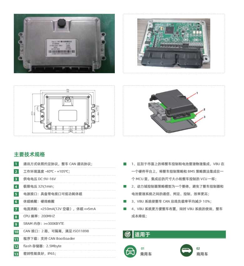
The EBX-960B collapses both functions into one ECU. The 200 MHz MCU hosts both the vehicle-control strategy and the BMS strategy on the same scheduler, with the BMS data path going directly into the strategy through shared-memory access instead of through the CAN bus. The result is the four design properties the source application notes as the VBU advantage:
- Strategy-model unification — the VBU runs a single integrated strategy model rather than two separate strategies that need to negotiate across the CAN. Removes the latency / negotiation overhead between the VCU strategy and the BMS strategy, improves the closed-loop response
- Vehicle CAN bus load reduction — the source design notes a typical ~10 % cut in vehicle-CAN bus load on a representative new-energy vehicle, simply by removing the VCU↔BMS message catalogue from the bus
- Mechanical / electrical simplification — one bracket, one harness branch, one connector face, one in-vehicle position. Easier to package on a tight-engine-bay / tight-battery-pack-side layout
- BOM cost reduction — one MCU + one housing + one connector + one harness branch + one qualification effort, against two of each on the two-box pattern
And critically: the EBX-960B keeps the same mechanical footprint as the EBX-960 VCU. Programmes upgrading from the two-box pattern keep the same bracket, the same harness routing and the same in-vehicle position — the VBU drops in where the VCU used to sit, and the BMS box just goes away.
Engineering details
- 200 MHz automotive MCU — sized to host both the vehicle-control strategy and the BMS strategy on the same scheduler without sacrificing the safety-relevant timing budget; the headline that makes the unification possible
- 300 KB SRAM + 2.5 MB Flash — large enough for the unified VCU + BMS application code, the per-platform calibration map, the diagnostic catalogue and the CAN-Bootloader image with margin for in-field FOTA upgrade
- 2 × galvanically-isolatable ISO 11898 CAN buses — the vehicle-network bus and the battery-pack bus can be run on separate physical CAN segments with optional galvanic isolation between them. Protects the vehicle bus from high-voltage transient pickup on the pack-side bus, and lets the programme isolate the battery network for diagnostic / safety purposes
- Hard-wire wake — the ECU sleeps at ≤ 5 mA and wakes on the KL15 / ignition event or on the BMS-side high-voltage interlock event, without polling the bus
- CAN-Bootloader OTA — firmware upgrade across the vehicle CAN without an external programmer; staged calibration map update for the vehicle-control side and the BMS side independently
- Extended −40 to +105 °C working temperature — +20 °C above the typical +85 °C cabin envelope; suitable for the engine-bay-equivalent compartment on an electric vehicle or directly adjacent to the battery pack where ambient temperatures run higher than the cabin
- IP65 sealing — dust-tight, low-pressure water-jet resistant; suitable for the typical battery-pack-side or engine-bay placement
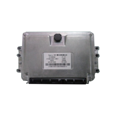
- Same footprint as EBX-960 VCU — mechanical drop-in upgrade path from the two-box VCU + BMS pattern to the unified VBU
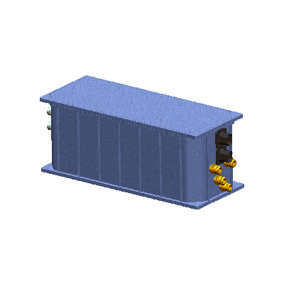
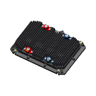
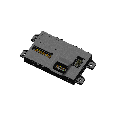
Mechanical and internal layout
Comparison with the EBX-960 VCU and the EBX-2305 BCM
| Model | Domain | MCU | BMS strategy integrated? | CAN bus load saving |
|---|---|---|---|---|
| EBX-960 | VCU (vehicle control only) | Standard automotive 32-bit | No (BMS is a separate ECU) | Baseline |
| EBX-960B | VBU (vehicle control + BMS unified) | 200 MHz automotive 32-bit | Yes (unified on same MCU) | ~10 % typical |
| EBX-2305 | New-energy BCM (body control) | Standard automotive 32-bit | Not in scope (body side) | n/a |
The EBX-960B is the right choice for a new-energy programme that wants to consolidate the VCU + BMS two-box pattern into one ECU, with the secondary benefit of cutting the vehicle-CAN bus load. For a programme that wants a pure VCU and a separate BMS supplier, look at EBX-960 VCU; for the body-control side of a new-energy programme, look at EBX-2305 New-Energy BCM.
Manufacturing & testing
Built under IATF 16949 with APQP project planning and a PPAP package available for OEM programmes. Every unit is end-of-line functional-tested before packaging — the dual CAN buses (each on the ISO 11898 physical-layer compliance check + galvanic-isolation continuity test), the wake-up event handling (sleep entry / wake-on-KL15 / wake-on-hardwire / return to active), the FOTA path via CAN-Bootloader (boot-loader hand-off / application-image flash / signature verification / application start), the SRAM / Flash integrity check, the active-current draw and the sleep-current draw across the supply range. Environmental validation and EMC pre-compliance screening per the customer-side new-energy profile (the EBX-960B profile typically includes the extended temperature scope up to +105 °C and the higher EMC hardness needed for placement directly adjacent to a high-voltage battery pack); run in our in-house lab.
How to ask
The EBX-960B belongs to the Smart Control Modules family. To request the harness drawing, the BMS algorithm scope (cell-balancing / SOC / SOH / contactor logic), the vehicle-control strategy scope (torque request / drive-mode / energy management), the CAN message catalogue or a PPAP package, please use the contact page with your target vehicle programme, battery-pack architecture (cell count, module count, contactor / pre-charge topology), expected annual volume and key technical requirements (target CAN bus load, FOTA scope, IP rating, in-vehicle position). Drawings welcome.