Overview — why a battery equaliser on a 24V system
A heavy truck or bus runs a 24V electrical system, built physically as two 12V batteries wired in series. Most of the vehicle's loads sit across the full 24V (starter, primary lighting, body-control bus, hydraulic-solenoid bank), but a non-trivial set of "12V auxiliary" loads is much easier to source on the 12V side: cabin radio, dash-cam, GPS telematics, USB charging, dash lighting, after-market accessories. The traditional simple approach is to tap one of the two series-stack 12V batteries directly to drive the 12V auxiliary loads.
That simple approach has a hidden problem: the 12V auxiliary load drains only one of the two batteries, while the alternator (or the EBX-2314 DCDC controller on an electric platform) charges both. Over many cycles the two batteries drift apart in state-of-charge — the tapped one runs progressively lower, the un-tapped one stays full. The un-balanced stack accelerates wear on the lower battery, eventually leading to a premature single-battery failure that pulls down the entire 24V system.
The standard fix is a battery equaliser that supplies the 12V auxiliary loads directly (instead of tapping one battery) and also actively balances the two batteries by transferring charge from the higher-SOC battery to the lower-SOC battery when they drift apart. The EBX-2407 does both functions on one ECU. The 24V system feeds the equaliser through the heavy-current input + / − terminals; the equaliser produces a regulated 12V output on the output + / − terminals that feeds the 12V auxiliary bus; and the on-board balancing stage monitors the two batteries' voltages (via the internal current sense and the input voltage measurement) and transfers charge between them when needed. The two SKUs (100 A and 30 A) cover the spectrum from heavy-load trucks / buses down to the lighter-load specialty-vehicle programmes.
Engineering details
IP67 + IP66K dual-rated housing
The housing carries two IP ratings together, which is a stricter envelope than either rating alone. IP67 means dust-tight + survives 30 minutes immersed in 1 m of water; IP66K (per ISO 20653) means powerful-water-jet resistant including the high-temperature high-pressure water-jet typical of a seasonal pressure-washer cleaning. The dual rating lets the equaliser sit chassis-side directly exposed to both wading events (driving through a puddle deep enough to immerse the equaliser) and pressure-washer cleaning — the typical heavy-truck / construction-machinery / off-road profile.
Finned aluminium housing + breather vent
The finned aluminium-alloy main housing handles the thermal-shedding requirement of the heavy-current DCDC stage. The breather vent in the bottom face equalises the internal-pressure across the day-night thermal cycle while maintaining the IP67/IP66K seal; without the vent, the housing would alternately suck air (cold) and exhale water-saturated air (hot) through the connector seals, eventually compromising them.
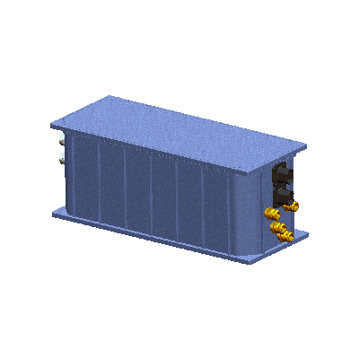
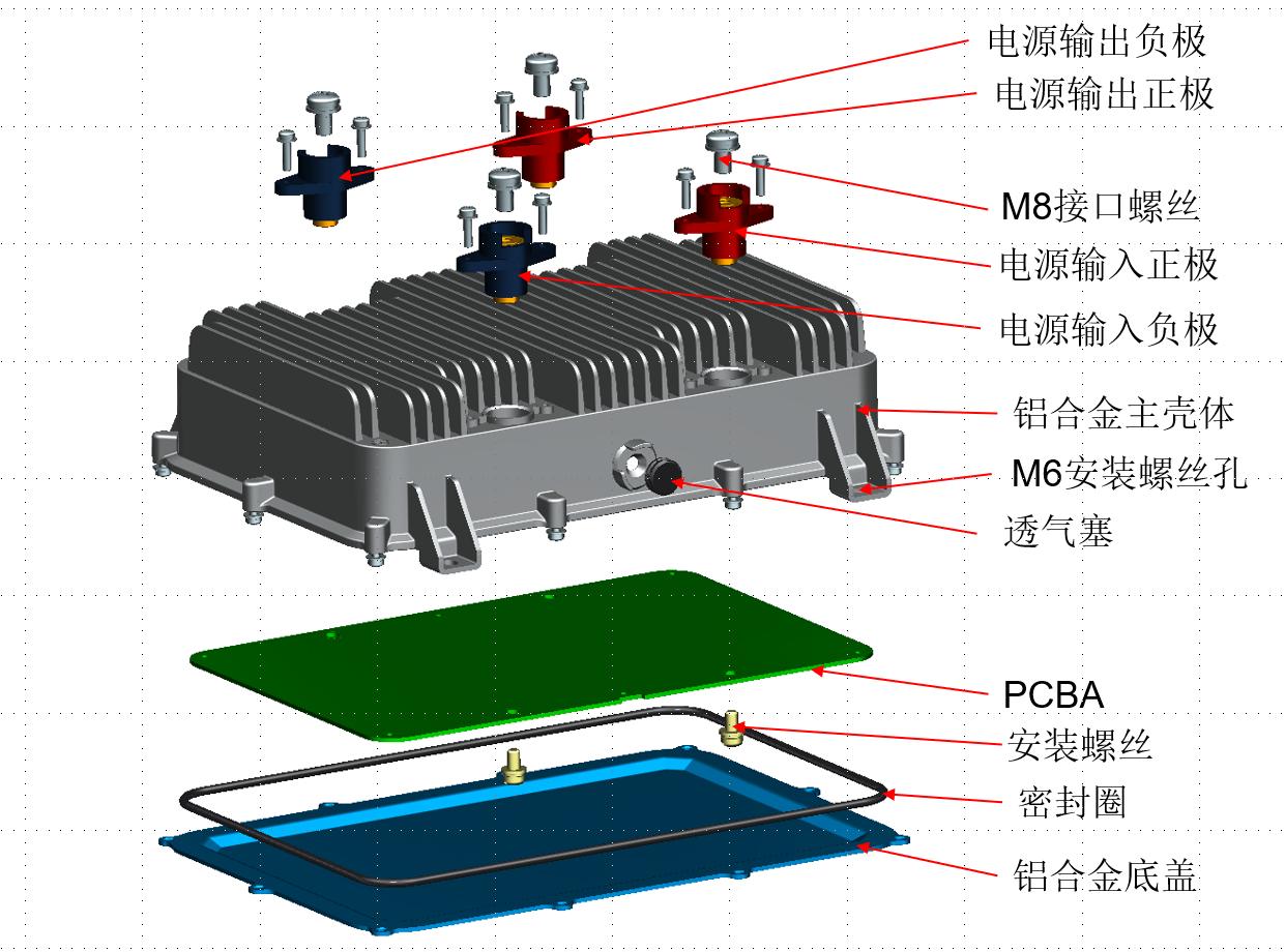
M8 power terminals
The four M8 stud power terminals (input + / − and output + / −) are sized for the heavy current of the 100 A SKU (up to 100 A on the output side). M8 stainless-steel power-bolts allow direct ring-terminal mounting of the heavy-current cable. The colour-coded caps (red for + and blue for −) keep the installation unambiguous on the assembly line. On the 30 A SKU the same M8 terminals are used (over-specified for the lower-current SKU but keeps a common housing across SKUs for simpler inventory).
CAN self-diagnostic
The equaliser monitors four state variables and dispatches a CAN exception message when any of them crosses the configured threshold:
- Input over-voltage > 32 V — protects the equaliser from a fault on the upstream alternator / DCDC; the equaliser self-shuts-down when over-voltage is detected
- Input under-voltage < 16 V — the 24V system has dropped to a level where the equaliser cannot reliably step down to 12V; the fleet-side scanner sees the input voltage drop before the 12V output collapses, helping diagnose a failing starter / alternator
- Output low-voltage < 12 V — the 12V output has dropped below the nominal 12V level despite the input being healthy; indicates an output-side load fault (short, near-short) or DCDC stage degradation
- Over-temperature > 80 °C — the equaliser body has reached the thermal-derate threshold; the controller auto-derates the output current to keep the body temperature in the safe envelope, and trips out completely if the over-temperature persists
The CAN exception messages let the fleet-side telematics tool and the workshop scanner see the same fault list, supporting predictive maintenance for the heavy-current electrical sub-system.
Housing exploded view and stack-up
Mechanical drawing
Comparison with the related Youlai power modules
| Model | Input → Output | Output current | IP grade | Functions |
|---|---|---|---|---|
| EBX-2407 | 24 VDC → 12 VDC | 100 A or 30 A SKU | IP67 + IP66K | Step-down + dual-battery balancing |
| EBX-2314 | 600 VDC (400-750) → 18-32 VDC | 36 kW rated / 40 kW peak (24V output) | Programme-spec | HV→24V DCDC + on-board pre-charge |
The EBX-2407 is the right choice for the 24V → 12V step-down + dual-battery balancing role on a 24V heavy-truck / bus electrical system. For the upstream HV → 24V DCDC role on an electric heavy-duty vehicle, look at EBX-2314 high-voltage DCDC controller.
Manufacturing & testing
Built under IATF 16949 with APQP project planning and a PPAP package available for OEM programmes. Every unit is end-of-line functional-tested before packaging — the 24V → 12V step-down output regulation under rated current (100A on the 100A SKU, 30A on the 30A SKU) with rise-time and ripple measurement, the dual-battery balancing function (verified by simulating a SOC differential between the two 12V series-stack batteries and observing the balancing-current transfer), the reverse-polarity tolerance up to −29 V on the input side, the CAN self-diagnostic dispatch on each of the four fault classes (over-voltage / input under-voltage / output low-voltage / over-temperature), and the IP67 immersion seal + IP66K powerful-water-jet seal baseline are all checked.
How to ask
The EBX-2407 belongs to the Smart Control Modules family. To request the harness drawing, the SKU selection (100 A vs 30 A) per your 12V auxiliary load profile, the CAN signal-ID assignment, the balancing-current-rate tuning option or a PPAP package, please use the contact page with your target vehicle programme, expected annual volume and key technical requirements (12V auxiliary load list and peak current, in-vehicle mounting position, thermal-environment ambient, IP rating, CAN signal-ID negotiation). Drawings welcome.