Overview — one-box PMU + power distribution
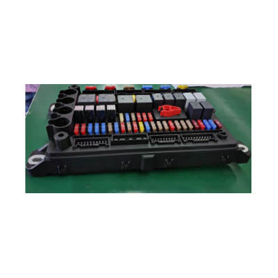
Most commercial-vehicle electrical architectures split the body-side electronics into two separate boxes: a smart-control ECU on one side and a power-distribution / fuse-relay box on the other, connected by an inter-box harness that carries every drive output from the ECU through the PDB and back out onto the actuator harness. This pattern is simple to design but it doubles the connector count, doubles the harness count and forces a wire to cross the cabin (or the chassis) twice for every actuator drive.
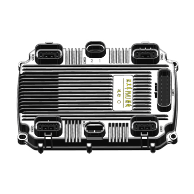
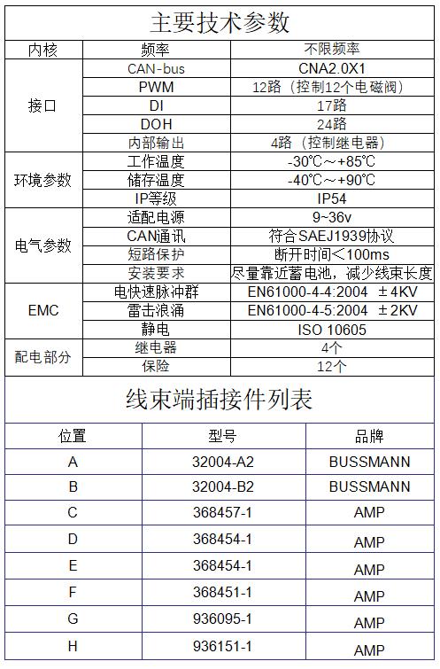
The EBX-2050 collapses both functions into a single housing. The smart-logic side carries the MCU, the SAE J1939 CAN front-end and the 12 PWM-capable HSD channels (typically allocated one per solenoid valve), the 17 digital inputs (typical use: vehicle-side switches, sensor digital outputs, interlock chains), the 24 high-side digital outputs (typical use: smaller-current accessory loads driven directly without going through a relay) and 4 internal relay drive outputs driving the integrated 4-relay sub-section. The power-distribution side carries 12 fuses (the program assigns each fuse to a specific drive channel or accessory load) plus the 4 relays driven internally from the MCU side — all in one housing with a central transparent service-access cap over the fuse / relay bay for fuse replacement without opening the box.
The result is a more compact harness, fewer connectors at the box-side bracket, no inter-box harness between the ECU and the PDB, and a single fault-isolation point for the body-side electrical sub-system (the diagnostic can locate a fault to either the smart-logic side or the power-distribution side from a single OBD-style scan rather than having to chase the fault across two boxes). A PMU like this owns power distribution and its protection, not the body-logic decisions a BCM makes or the torque-and-energy strategy a VCU runs; for where those boundaries fall, see the BCM vs VCU vs PMU comparison.
I/O capability set
12 × PWM-capable HSD channels (typical: solenoid drive)
The 12 PWM-capable high-side-driver channels are the primary actuator interface of the EBX-2050. The typical use is one-per-solenoid-valve on a hydraulic-rich programme (e.g. a special-purpose vehicle with a dozen hydraulic valves — lift, tilt, swing, tail-gate, top-cover, side-door, work-light, washer, etc.), with the PWM modulation tuned per valve to control the dwell / hold-current profile. Each channel runs the smart HSD protection envelope described below.
17 × digital inputs (DI)
The 17 digital input lines absorb the program's switch / sensor inventory — vehicle-side switches, position-limit feedback from the actuator side, interlock-chain confirmations, sensor digital outputs (e.g. pressure-switch, level-switch).
24 × high-side digital outputs (DOH)
The 24 high-side digital outputs are dedicated to smaller-current accessory loads that don't need PWM modulation — indicator lamps, secondary accessory relays, status LEDs, accessory power tap-offs. These channels run a fixed on / off output without the PWM stage of the 12 PWM channels.
4 × internal relay drive outputs
The 4 internal relay drive outputs drive the 4 relays integrated into the power-distribution sub-section of the same housing — typically allocated to the highest-current accessory loads (work-light banks, secondary motor drives, accessory heater / blower power, large pump motors) where a solid-state HSD would not survive the in-rush current.
Integrated 12-fuse power-distribution side
The 12-fuse + 4-relay sub-section is built into the same housing. Each fuse is assigned to a specific drive channel or accessory load per the programme's allocation matrix (confirmed at quotation). Fuse rating per channel is selected per the load class. The central transparent service-access cap on top of the housing lets the workshop replace a blown fuse without opening the sealed housing — an important field-maintenance feature for high-actuator-count programmes where the per-fuse cycle count is non-trivial.
Smart HSD protection envelope
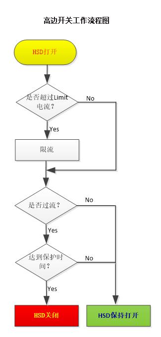
Every PWM and HSD channel runs the same per-channel smart-protection state machine. The state machine has four decision points per channel:
- HSD turn-on → the channel drives the load with the programmed PWM / on-state
- Current-limit (Limit) check — is the channel current above the configured Limit threshold? If no, the channel stays on; if yes, the channel enters current-limit mode (limit-current is supplied but the limit threshold is enforced, protecting the driver against an over-current event from a startup in-rush or a partial-short fault)
- Over-current check — once in current-limit mode, the state machine then checks whether the over-current condition has cleared. If no (over-current cleared), the channel returns to normal drive (HSD stays on); if yes (over-current persists), the state machine starts the protect-time timer
- Protect-time check — has the protect-time threshold been reached? If no, the channel stays in limit-current mode; if yes (the over-current condition has persisted for the full protect-time), the channel is HSD-turned-off and the per-channel fault flag is asserted on the J1939 diagnostic message
The protection envelope keeps the channel running through a startup in-rush event (the limit-current absorption gives the load time to reach steady-state without the channel tripping), but does properly trip on a sustained over-current event (a stuck actuator, a partial short or a wiring fault). Auto-re-enable on cool-down lets the channel come back online without driver intervention once the fault clears.
Engineering details
- Single-housing PMU + power distribution — eliminates the separate PDB / NBX box, removes the inter-box harness, halves the connector count at the box-side bracket; single fault-isolation point for the body-side electrical sub-system
- SAE J1939 CAN compliance — the smart-logic side speaks J1939 to the upstream BCM, with each channel's drive command and each channel's diagnostic flag on the J1939 message catalogue; the program can DM1-poll the controller from any J1939-compliant diagnostic tool
- Smart per-channel HSD protection envelope — current-limit + over-current + protect-time trip + auto-re-enable + per-channel J1939 diagnostic flag
- EN 61000-4-4 ±4 kV EFT + EN 61000-4-5 ±2 kV surge + ISO 10605 ESD — the EMC scope is at the heavy-truck / construction-machinery hardness level rather than the lighter passenger-vehicle profile, suitable for the kind of programmes where the controller sits close to a heavy battery or close to an inductive solenoid bank
- Eight sealed connector face — 2 Bussmann heavy-current power input connectors + 4 AMP signal connectors + 2 AMP medium-current actuator connectors; the split lets the harness designer keep the heavy-current side physically separated from the signal side, which is critical for the signal-side integrity when the heavy-current side is switching high-PWM-duty inductive loads
- Central transparent service-access cap over the 12-fuse + 4-relay bay — field replacement of a blown fuse without opening the sealed housing; the cap is itself sealed
- IP54 protection grade — dust-protected, splash-protected; suitable for the typical engine-bay placement near the battery (for chassis-side mounting exposed to road-spray, the IP66 EBX-2052 is the sealed sibling)
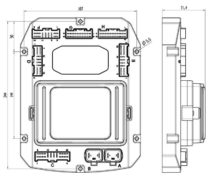
- Install close to the battery per the harness-drawing guidance — minimises the heavy-current harness length on the battery-input side, reducing voltage drop and EMC pickup; the smart-logic-side harness can run to the cab without the heavy-current burden
Mechanical layout
Technical reference (regulations / connector P/Ns)
Comparison with the related Youlai PMU modules
| Model | Integrated PDB? | I/O scope | Connector count | IP grade |
|---|---|---|---|---|
| EBX-2050 | Yes (12 fuses + 4 relays) | 12 PWM + 17 DI + 24 DOH | 8 sealed | IP54 |
| EBX-2052 | Yes (heavier-current Bussmann power side) | 16 PWM (15A & 9A) + 15 DI + 7 DO (incl. 2 × 50A high-current) | 7 sealed | IP66 |
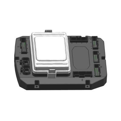
| EBX-2160 | Yes (60+ fuses + 11 relays, larger CPD) | CAN-side network drive only | Larger | IP53 |
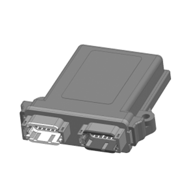
| EBX-962 | No (pure smart-logic side) | 8 HSD-PWM + 4 DI/AI + CAN | 2 sealed | IP65 |
The EBX-2050 is the right choice when a programme wants both the smart-logic side and the power-distribution side in a single ECU, with a 12-solenoid hydraulic-rich actuator scope and J1939-compliant fleet diagnostics. For a higher-current PMU with up to 50 A direct DO channels and IP66 sealing, look at EBX-2052; for a much larger central power-distribution ECU (60+ fuses, 11 relays), look at EBX-2160 CPD; for a pure CAN-attached smart-logic I/O extension (no integrated PDB), look at EBX-962.
Manufacturing & testing
Built under IATF 16949 with APQP project planning and a PPAP package available for OEM programmes. Every unit is end-of-line functional-tested before packaging — the 12 PWM channels (each across full-on, full-off and a typical PWM duty + waveform integrity), the 24 HSD outputs, the 4 internal relay drive outputs with the integrated relay-coil load present, the 17 digital inputs across the full input range, the smart-HSD protection envelope (Limit-trip + over-current trip + protect-time trip + auto-re-enable cycle), the SAE J1939 CAN bus health and the integrated fuse-bay continuity are all checked. EMC pre-compliance screening per EN 61000-4-4 / -4-5 / ISO 10605 is run in our in-house lab.
How to ask
The EBX-2050 belongs to the Smart Control Modules family. To request the harness drawing, the per-fuse / per-relay allocation matrix, the per-PWM-channel current/dwell tuning option, the J1939 message catalogue or a PPAP package, please use the contact page with your target vehicle programme, expected annual volume and key technical requirements (number of solenoid valves + per-valve current / dwell profile, high-current accessory load list, J1939 message scope, EMC profile, IP rating, connector preference). Drawings welcome.