Overview
A centralised BCM — for example the EBX-952, EBX-953 or EBX-954 — carries a fixed connector face that was sized for the program's baseline harness. Once the program is in production, every new variant that wants to add an accessory pack (a regional lift-axle, a fleet-spec light-bar, a dump-bed function group, an auxiliary heater, an idle-stop-start interlock or a regional regulation accessory) runs into the same problem: the BCM's harness pins are all spoken for. Adding the accessory means either swapping the BCM SKU (massive retest + recertification cost) or running an aftermarket box on the side that the BCM cannot really see.
The EBX-962 solves this problem as a dedicated CAN-attached I/O expansion box. It plugs onto the body CAN bus and presents the BCM with eight more configurable high-side-driver PWM outputs (each one switchable to a digital input), four more configurable digital-or-analog inputs, two more interrupt-capable inputs and a pair of 12 V auxiliary supply outputs — sized to add a complete regional accessory pack without any change to the main BCM SKU. The CAN message catalogue is per programme; typical patterns are a transparent virtual-I/O message profile (the BCM reads / drives the EBX-962's pins as if they were its own) or an event-driven profile (the EBX-962 reports input transitions and the BCM dispatches drive commands).
Integrated capability set
8 × HSD-PWM outputs reconfigurable as digital inputs
The eight A05–A12 channels are the heart of the EBX-962. Each channel is a high-side-driver gate with PWM-capable output mode (DO_H_PWM) that can drive an external accessory load with adjustable duty cycle (typical use: relay coil, accessory bulb dimming, fan-speed control via PWM, indicator LED) — or be reconfigured (per-channel, in firmware) as a digital input (DI_IOC_H), so the BCM can read a high-active accessory switch on that pin instead of driving an output. The eight-channel reconfigurable IO bank is what gives the EBX-962 its "extra hand" reputation — the program does not need to commit at design time to a fixed output / input split.
2 × +12 V auxiliary supply rails
Connector B carries two +12 V auxiliary output rails (B02 / B03) — useful when the regional accessory pack includes a 12 V sensor (e.g. a fluid-level switch, a flow sensor, a Hall-effect rotary input, a discrete IR sensor) and the program does not want to add a separate sensor-side step-down DC-DC. The 12 V rails are derived from the controller's internal supply and are protected per the four-fold protection set.
4 × configurable digital-or-analog inputs
B04 / B05 / B10 are configurable as digital-high-active or digital-low-active inputs (DI_H/L); B08 / B09 are configurable as analog voltage-input (AI_U) or analog current-input (AI_I) — lets the program plug 0–5 V, 0–10 V or 4–20 mA sensor outputs directly without an external signal-conditioning circuit.
2 × interrupt-capable digital inputs
A03 / A04 are interrupt-capable low-active digital inputs (DI_L_INT) and B11 is an interrupt-capable high-active digital input (DI_H_INT). The interrupt capability means the firmware can publish an input-edge CAN message within microseconds of an edge — useful for emergency-stop chains, door-open sense and crash-sense accessory inputs where the time-to-CAN matters.
1 × CAN bus
The single CAN port is the EBX-962's communication channel to the rest of the vehicle. The message catalogue is per programme — typical patterns are a transparent virtual-I/O profile (one CAN message carries all eight HSD-PWM output commands plus the four DI/AI input states) or an event-driven profile (input edges trigger publish, output commands trigger drive). The EBX-962 can also be slaved off the EBX family's EBX-2301 vehicle network gateway when the program runs multiple CAN segments and wants the accessory pack on its own segment.
Engineering details
- Four-fold safety protection on each high-current drive channel — particularly important on the HSD-PWM outputs where the accessory load is unknown at design-time (could be a relay coil, an LED bar, a small fan, a heater element)
- Per-channel HSD output / digital-input switchability — the eight A05–A12 channels are configurable individually (any channel can be output, any channel can be input) at firmware-load time, so the program does not need to commit at design time to a fixed output / input split
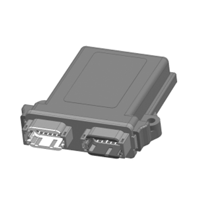
- IP65 sealing class — one class higher than the EBX-2162/3/4 platform's IP53; suitable for in-cab placement but also for partially exposed positions (engine-bay periphery, behind-bumper accessory boxes)
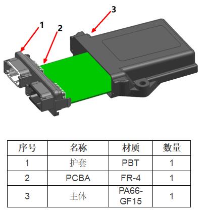
- Glass-fibre reinforced PA66-GF15 housing — dimensional stability across temperature, low warpage, impact-resistant for cab-side or partially-exposed positions
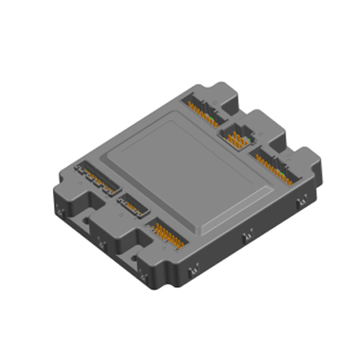
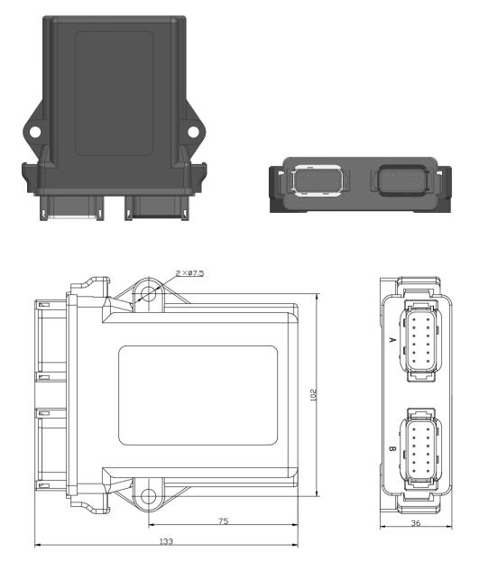
- Compact 133 × 102 × 36 mm body — takes a small footprint on the cab-side bracket; the dual 12-pin connector face is on a single short edge of the housing for easy harness routing
- Free-orientation mounting on the two Φ7.5 mm side through-holes
- Single CAN port — clean integration into the body CAN backbone or into a dedicated accessory CAN segment downstream of a network gateway
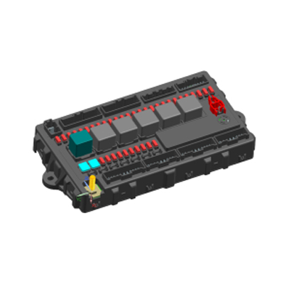
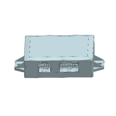
Mechanical layout
Construction
24-pin pin-out reference
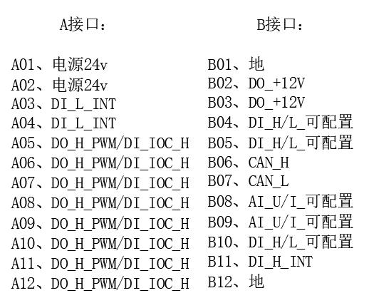
The standard build lands all signals across the two sealed 12-pin connectors per the reference pin-out below. Final pin allocation is confirmed against the customer harness drawing at quotation.
| Pin | Connector A (drive-side) | Pin | Connector B (input + CAN side) |
|---|---|---|---|
| A01 | Power +24 V | B01 | Ground |
| A02 | Power +24 V | B02 | DO_+12 V auxiliary output |
| A03 | DI_L_INT (interrupt-capable low-active digital input) | B03 | DO_+12 V auxiliary output |
| A04 | DI_L_INT (interrupt-capable low-active digital input) | B04 | DI_H/L (configurable digital input) |
| A05 | DO_H_PWM / DI_IOC_H (reconfigurable) | B05 | DI_H/L (configurable digital input) |
| A06 | DO_H_PWM / DI_IOC_H (reconfigurable) | B06 | CAN-H |
| A07 | DO_H_PWM / DI_IOC_H (reconfigurable) | B07 | CAN-L |
| A08 | DO_H_PWM / DI_IOC_H (reconfigurable) | B08 | AI_U/I (configurable analog input) |
| A09 | DO_H_PWM / DI_IOC_H (reconfigurable) | B09 | AI_U/I (configurable analog input) |
| A10 | DO_H_PWM / DI_IOC_H (reconfigurable) | B10 | DI_H/L (configurable digital input) |
| A11 | DO_H_PWM / DI_IOC_H (reconfigurable) | B11 | DI_H_INT (interrupt-capable high-active digital input) |
| A12 | DO_H_PWM / DI_IOC_H (reconfigurable) | B12 | Ground |
Typical pairing patterns
| Main BCM | Use case for EBX-962 |
|---|---|
| EBX-952 (24 V compact BCM) | Add a regional accessory pack (work-light bar + auxiliary heater + dump-bed switch group) without redesigning the BCM |
| EBX-953 (24 V BCM + integrated fuse / relay) | Add 8 more PWM-capable lighting outputs for a tractor-trailer auxiliary-lighting program |
| EBX-954 (24 V heavy-truck BCM, pure logic) | Add a configurable DI / AI bank for a fleet-spec sensor pack (load, fuel-flow, oil-pressure) |
| EBX-2301 (vehicle network gateway) | Slave the EBX-962 to a dedicated accessory CAN segment downstream of the gateway, keeping the body CAN clean |
Manufacturing & testing
Built under IATF 16949 with APQP project planning and a PPAP package available for OEM programmes. Every unit is end-of-line functional-tested before packaging — the 8 HSD-PWM outputs (PWM at the typical range plus full-on and full-off), the 8 channels' reconfiguration into digital-input mode, the 4 configurable DI/AI inputs across the full digital and the full analog ranges, the 3 interrupt-capable inputs, the dual +12 V auxiliary supply rails, the CAN bus health and the four-fold safety-protection envelope (over-voltage / over-current / short-circuit / over-temperature trip and recovery) are all checked.
How to ask
The EBX-962 belongs to the Smart Control Modules family. To request the harness drawing, the CAN message catalogue option (transparent virtual-I/O vs event-driven), the per-channel HSD-PWM rating, the analog-input scaling option or a PPAP package, please use the contact page with your target vehicle programme, expected annual volume and key technical requirements (main BCM model + CAN protocol, accessory-pack drive scope and rating, sensor-pack analog standard, IP rating, connector preference). Drawings welcome.