Overview
The EBX-960 is a dedicated new-energy vehicle control unit (VCU) — the top-of-stack powertrain ECU that owns the high-voltage / low-voltage power-up & power-down sequencing, parses the driver inputs (accelerator pedal, brake pedal, gear selector), arbitrates the torque request across competing priorities (driver, ESP, energy management, torque-limit policy), forwards the torque / direction command to the motor controller and runs the energy-recuperation and auxiliary-management policy. Where a body-control module such as the EBX-2305 owns the body-electronics scope on a new-energy passenger vehicle, the EBX-960 sits one layer up — on the powertrain side, between the battery management system / charger / motor controller and the rest of the vehicle. For how the VCU compares with the BCM and PMU it shares the network with, see the BCM vs VCU vs PMU comparison.
Electrically the EBX-960 takes a 7 – 48 VDC wide-range supply, which means the same hardware platform fits a 12 V passenger-vehicle architecture, a 24 V commercial-vehicle architecture and a 48 V mild-hybrid architecture without needing a hardware change. The CPU is a 32-bit automotive MCU running at 200 MHz with ≥ 300 KB SRAM and 2.5 MB Flash, sized for an embedded vehicle-control software stack that includes the torque-arbitration loop, the gear-state machine and the energy-management policy — with headroom for the program-specific calibration tables.
13 integrated VCU functions
1. HV / LV power-up sequencing
The VCU owns the ordered closure of the contactors / pre-charge circuit on the high-voltage side and the corresponding low-voltage rail wake-ups on the auxiliary side — from key-on through pre-charge to main-contactor closure to ready-to-drive, with the program-defined timing and the program-defined fault-handling on each transition.
2. HV / LV power-down sequencing
The matching ordered shutdown — controlled discharge of the DC-link capacitor through the pre-charge resistor (where the architecture uses one), main-contactor open, auxiliary-rail wind-down and persistent-state save to non-volatile memory.
3. Gear management
Gear-selector input parsing (P / R / N / D state), gear-shift permission against the vehicle-speed / brake-pressed / driver-presence interlock set, and the gear-state forwarding to the motor controller and the cluster.
4. Accelerator-pedal parsing
Dual-channel accelerator-pedal signal acquisition (typical APS-1 + APS-2 redundant channels), plausibility check on the inter-channel ratio, fault-handling on out-of-range / channel-mismatch / open-circuit / short-circuit per the program's APS diagnostic profile.
5. Brake-pedal parsing
Brake-switch and brake-pedal-position acquisition, plausibility check between the switch state and the pedal-position rate of change, and the forward to the brake-priority arbitration block (function 9 below).
6. Torque arbitration
Torque-request resolution between the driver demand (from the accelerator pedal), the torque-limit policy (from the BMS state-of-charge / state-of-temperature limits), the brake-priority override and any external torque request (ESP / ABS / cruise / regenerative). The arbitrated torque target is forwarded to the motor controller.
7. Motor torque / direction control
The arbitrated torque command and the corresponding motor-direction command (forward / reverse) are forwarded to the motor controller over CAN, with the direction interlocked against the gear state and the vehicle-speed state.
8. SPORT mode
A driver-selectable performance profile that re-shapes the pedal-to-torque map (typically more aggressive pedal response, raised torque ceiling within the BMS limits and adjusted regenerative-braking blend).
9. Torque limiting
Torque ceiling driven by the energy-source state (BMS SOC / SOT limits), the motor-controller state and any program-specific limit-policy entry (e.g. wheel-slip, ESP-active, low-speed creep, valet mode).
10. Brake-priority
Brake-priority override on the arbitrated torque request — when the brake-pedal signal is asserted and the plausibility check passes, the driver-demand torque is overridden / zeroed per the program's brake-priority policy (typical SAE J3018 / OEM-specific safety policy).
11. Energy recuperation
Regenerative-braking blend between the friction-brake demand and the motor-side regenerative torque, with the regen capacity dimensioned by the BMS state-of-charge / state-of-temperature headroom and the wheel-side traction-limit set.
12. Auxiliary management
Auxiliary-rail control (HVAC compressor / PTC heater / DC-DC enable / vacuum-pump for the brake booster) under the energy-management policy — load shedding under low-SOC, climate priority under HV-charging, and the corresponding cluster / driver-side messaging.
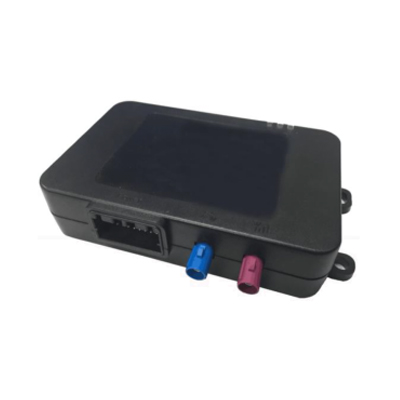
13. Remote-control interface
Remote-control entry point (typical CAN gateway forward from the T-BOX / telematics module — e.g. the EBX-2054 T-BOX) for remote high-voltage power-up, remote climate pre-conditioning and remote diagnostic / charge-state query.
Engineering details
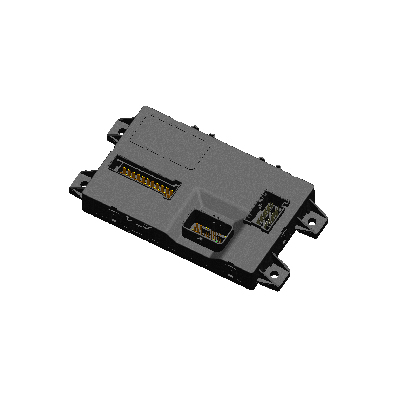
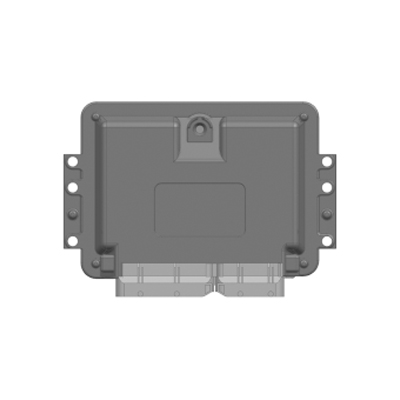
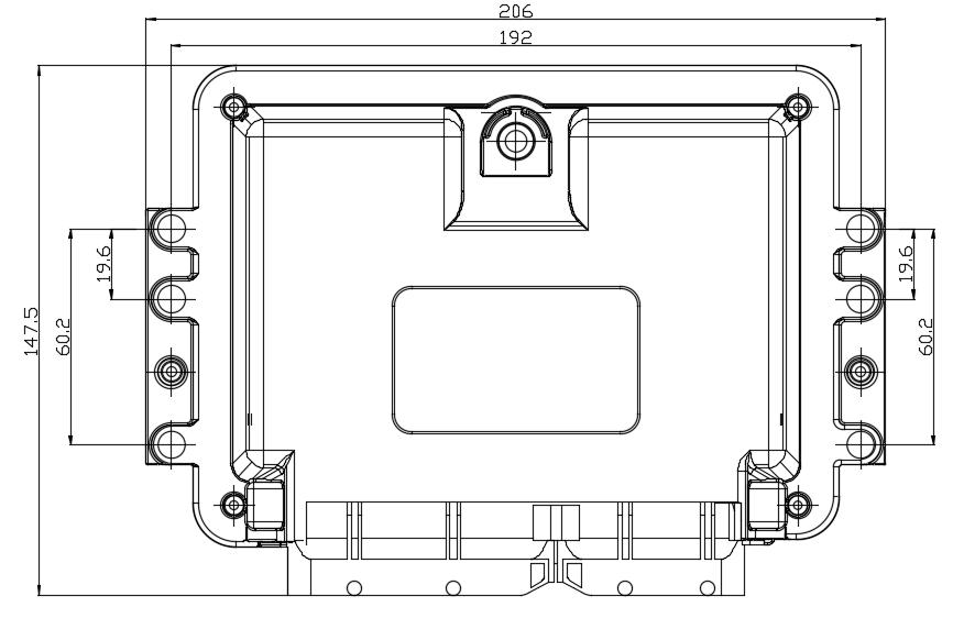
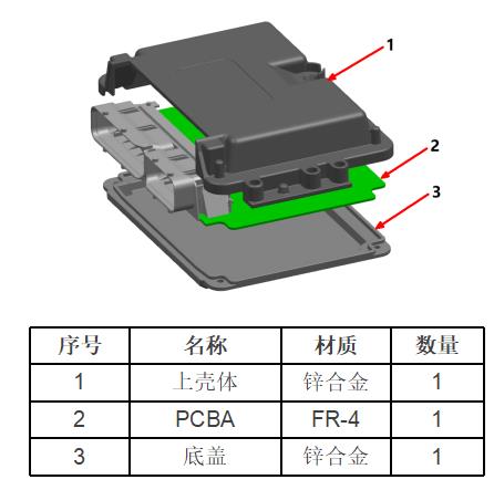
The EBX-960 occupies a 206 × 147.5 mm footprint (192 mm body width over the housing, 206 mm over the four corner mounting ears) and lands on four through-hole mounting points (19.6 mm horizontal pitch × 60.2 mm vertical pitch on each side). The cast zinc-alloy upper + lower housing gives the high-thermal-mass / high-mechanical-rigidity envelope needed for a powertrain-side ride-along position; the FR-4 PCBA sits between the two halves under environmental three-coat conformal-coating.
- 7 – 48 VDC wide-range supply — one hardware platform fits 12 V / 24 V / 48 V vehicle architectures; the front-end DC-DC accepts the full range and presents the regulated logic rails internally
- Operating temperature −40 to +105 °C — high-temperature rated, suitable for engine-bay / powertrain ride-along positions and for ambient extremes typical of commercial-vehicle deployments
- 200 MHz 32-bit automotive MCU with ≥ 300 KB SRAM and 2.5 MB Flash — sized for the torque-arbitration loop + gear-state machine + energy-management policy with headroom for program-specific calibration tables
- 2 × CAN, isolatable, ISO 11898-compliant — one channel typically rides on the powertrain backbone (BMS / motor controller), the other on the body / chassis backbone; the isolatable option keeps a powertrain-side fault from migrating onto the body-side network
- CAN Bootloader on the standard build — in-vehicle software update over the CAN backbone, no removal needed for re-flash
- Always-on (KL30) supply with low-power sleep capability — sleep current ≤ 5 mA, working current < 250 mA at 12 V no-load
- Cast zinc-alloy upper + lower housing — FR-4 PCBA between the two halves with environmental three-coat conformal-coating; the high-thermal-mass enclosure is the right pattern for an under-hood / powertrain-side ride-along ECU position
- IP65 sealing — dust-tight, splash-protected from all directions; suitable for under-hood / powertrain-side placement, with the harness side facing down
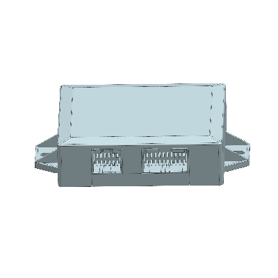
Mechanical layout
Construction (zinc-alloy + FR-4 PCBA)
Comparison with other Youlai control modules
| Model | Tier | Voltage | Working temp. | Enclosure |
|---|---|---|---|---|
| EBX-960 | New-energy VCU (powertrain top) | 7–48 VDC | −40 to +105 °C | Cast zinc-alloy / IP65 |
| EBX-2305 | New-energy BCM (body side) | 9–16 VDC | −40 to +85 °C | Polymer / in-cabin |
| EBX-2160 | Central PDB (CPD) | 18–32 VDC | −40 to +85 °C | Polymer / in-cabin |
| EBX-2054 | T-BOX (telematics) | 10–32 VDC | −30 to +70 °C | Polymer / in-cabin |
The EBX-960 is the right choice for any new-energy program that needs the dedicated powertrain-side VCU role — particularly when the program wants one hardware platform that covers 12 V passenger-vehicle, 24 V commercial-vehicle and 48 V mild-hybrid architectures, and when the ECU position is on the powertrain side (engine bay, powertrain ride-along, sealed under-hood). For the body-side companion BCM, look at EBX-2305; for the telematics-side companion T-BOX with cellular WAN, look at EBX-2054.
Manufacturing & testing
Built under IATF 16949 with APQP project planning and a PPAP package available for OEM programmes. Every unit is end-of-line functional-tested before packaging — the 7 – 48 V wide-range supply across the full input span, the 200 MHz MCU boot-up, the CAN1 / CAN2 communication on both isolated and non-isolated modes, the CAN Bootloader handshake, quiescent current in sleep, working current in active mode, and the hard-wire wake-up loop are all checked. Environmental validation and EMC pre-compliance screening in our in-house lab follows the OEM programme profile; the IP65 enclosure validation follows our IP-rating test procedure.
How to ask
The EBX-960 belongs to the Smart Control Modules family. To request the harness drawing, the per-pin allocation across the four harness connectors, the CAN message catalogue, the calibration-toolchain documentation or a PPAP package, please use the contact page with your target vehicle programme, expected annual volume and key technical requirements (vehicle architecture 12/24/48 V, BMS / motor-controller vendor and CAN protocol, target operating environment, calibration toolchain). Drawings welcome.