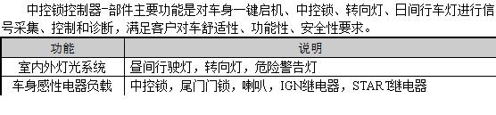
Overview — one box for four function groups
An entry-trim commercial vehicle's cabin function set is too small to justify a full-scope BCM and too large to leave to a handful of discrete relays and modules. The traditional path lands somewhere in the middle: a dedicated central-lock controller, a separate one-button-start module (or a key-in-ignition with a discrete IGN relay), a discrete electronic turn-signal flasher and a separate DRL driver — four modules behind the dashboard, four wiring branches and four spare-parts SKUs to manage.
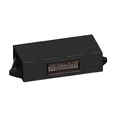
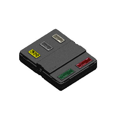
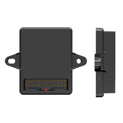
The EBX-2405 collapses all four function groups into one ECU on one 26-pin TE 936098-1 sealed connector. The 26-pin connector carries everything: the high-current relay-30 contacts for central-lock lock / unlock (15 A each), the medium-current relay-30 contact for tail-gate unlock (5 A) and for the DRL drive (5 A), the high-side-driver outputs for the two turn-signal lamps (4 A each), the relay-coil drive outputs for the START / IGN / horn relays (0.2 A each), the low-current work-indicator drive (0.1 A) and all the input lines (vehicle-speed, brake, hazard switch, door-ajar, lock-state feedback, START button, central-lock switch with analog read for lock / unlock differentiation, left / right turn-signal switches).
Four function groups walk-through
1. Central-locking (lock + unlock + tail-gate-unlock)
The central-lock sub-system uses three relay-30 contacts on the connector face: pin 23 (lock-unlock R30 / 15 A), pin 24 (lock-lock R30 / 15 A) and pin 25 (tail-gate unlock R30 / 5 A). The 15-amp contacts are sized for the typical direct-drive central-lock motor pair without an external relay; the 5-amp tail-gate contact is sized for the tail-gate solenoid or motor. The central-lock switch input on pin 16 is an analog read (the controller distinguishes lock vs unlock from a resistor-divider on the switch side, so a single wire to a 3-position switch handles the user input). Pin 3 carries the lock-state feedback signal from the door-side lock-state switch with interrupt-capable wake — lets the controller react to a manual unlock from the door cylinder without polling.
2. One-button-start sequencer
The one-button-start sub-system uses the START button input on pin 17 (interrupt-capable wake) plus the brake interlock on pin 20 (the brake-signal high-active input). When the operator presses START with the brake pedal down, the firmware sequencer drives the IGN relay coil (pin 13, HSD 0.2 A) high, waits the program-defined dwell, drives the START relay coil (pin 12, HSD 0.2 A) high to crank the engine, releases START on engine-running confirmation, drives the work-indicator lamp (pin 10, HSD 0.1 A) on. A second press without the engine running aborts the sequence; a second press with the engine running drives the engine-off sequence (IGN relay coil released after a safety dwell). The horn relay (pin 11, LSD 0.2 A) is wired into the system as an audible-confirmation tap for security-event annunciation.
3. Full turn-signal drive (left + right + hazard)
The turn-signal sub-system uses two high-side-driver outputs: pin 18 (right turn-signal lamp drive, HSD 4 A) and pin 19 (left turn-signal lamp drive, HSD 4 A). The 4 A drive class is sized for the typical filament-bulb turn-signal lamp pair without an external flasher relay. The hazard-flash input on pin 2 (DIL with interrupt-capable wake) gates the firmware to flash both turn-signal outputs simultaneously at the regulation-defined flash rate. The left / right turn-signal switch inputs on pins 5 / 6 provide the directional flash command.
4. Daytime-running-light (DRL) control
The DRL sub-system uses the relay-30 contact on pin 26 (DRL R30 / 5 A) for direct drive of the DRL lamp pair, gated on the vehicle-speed signal (pin 1, DIH). The firmware enables the DRL when the vehicle is in motion and the operator has not asserted a higher lighting state (e.g. low-beam, fog-lamp from another controller); the DRL is auto-disabled below a threshold speed to reduce idle-side power draw.
Engineering details
- Four function groups on one ECU — central-lock + one-button-start + turn-signal + DRL, replacing four discrete modules and the inter-module harness with a single 26-pin connection
- High-current R30 relay contacts for central-lock — 15 A direct drive eliminates the external central-lock relay typical of the discrete-controller arrangement
- 4 A HSD turn-signal drive — eliminates the external flasher relay; the firmware flasher logic provides the regulation-defined flash rate
- Analog-read central-lock switch input — one wire to a 3-position switch handles lock / unlock differentiation via resistor-divider
- Interrupt-capable wake inputs on the lock-state feedback, hazard switch, door-ajar switch and START button — the controller can sleep with ≤ 5 mA quiescent and wake on any of the user-relevant events without polling
- Vehicle-speed-gated DRL — reduces idle-side power draw and meets the typical regulation profile for DRL behaviour
- Wide 9-36 VDC supply — same SKU usable on 12 V (microvan / pickup) and 24 V (light truck) platforms
- Single 26-pin TE 936098-1 connector — industry-standard automotive sealed connector with wide global availability for the matching wire-side housing, terminals and seals
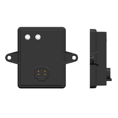
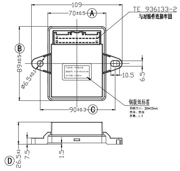
- Compact 109 × 89 × 26.5 mm body — takes a small footprint behind the dashboard
Mechanical layout
26-pin pin-out reference
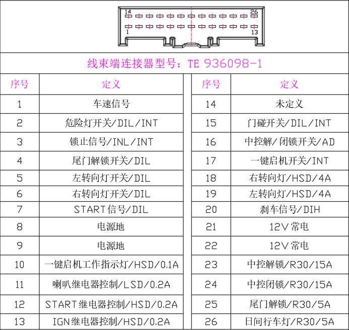
| Pin | Definition | Pin | Definition |
|---|---|---|---|
| 1 | Vehicle-speed signal (DIH) | 14 | Undefined (reserved) |
| 2 | Hazard-lamp switch (DIL / INT wake) | 15 | Door-ajar switch (DIL / INT wake) |
| 3 | Lock-state feedback signal (INL / INT wake) | 16 | Central-lock switch (AD analog read for lock / unlock differentiation) |
| 4 | Tail-gate unlock switch (DIL) | 17 | One-button-start press input (INT wake) |
| 5 | Left turn-signal switch (DIL) | 18 | Right turn-signal lamp drive (HSD 4 A) |
| 6 | Right turn-signal switch (DIL) | 19 | Left turn-signal lamp drive (HSD 4 A) |
| 7 | START signal (DIL) | 20 | Brake signal (DIH) |
| 8 | Power ground | 21 | +12 V always-on supply |
| 9 | Power ground | 22 | +12 V always-on supply |
| 10 | One-button-start work-indicator lamp (HSD 0.1 A) | 23 | Central-lock unlock (R30 / 15 A) |
| 11 | Horn relay control (LSD 0.2 A) | 24 | Central-lock lock (R30 / 15 A) |
| 12 | START relay control (HSD 0.2 A) | 25 | Tail-gate unlock (R30 / 5 A) |
| 13 | IGN relay control (HSD 0.2 A) | 26 | Daytime-running-light (R30 / 5 A) |
Function-scope reference
Comparison with related Youlai body controllers
| Model | Pattern | Pin count | Central-lock R30? |
|---|---|---|---|
| EBX-2405 | Integrated 4-function box (central-lock + one-button-start + turn-signal + DRL) | 26 (single TE) | Yes (15A + 15A + 5A) |
| EBX-2315 | 24 V Electric-Window & Mirror + Central-Lock | Single housing | Yes |
| EBX-2313 | Light-Truck BCM (12 V class) | Larger | Yes (part of BCM scope) |
The EBX-2405 is the right choice when an entry-trim light-commercial / microvan / specialty programme wants the four core cabin functions on a single ECU with a single-connector simple harness, without the cost / complexity of a full-scope BCM. For a programme that also wants integrated electric-window and mirror-adjust control, look at EBX-2315; for a full-scope light-truck BCM with the comprehensive body-function set, look at EBX-2313.
Manufacturing & testing
Built under IATF 16949 with APQP project planning and a PPAP package available for OEM programmes. Every unit is end-of-line functional-tested before packaging — the central-lock relay-30 contacts (lock / unlock / tail-gate-unlock loaded at rated current with contact-resistance measurement), the one-button-start sequencer (START / IGN / horn relay coil drive with simulated brake interlock and engine-running feedback), the turn-signal HSD outputs (4 A drive across left, right and hazard-flash modes), the DRL R30 contact gated by simulated vehicle-speed, the analog-read central-lock switch input across the resistor-divider profile, and all the digital inputs across the full input range are all checked.
How to ask
The EBX-2405 belongs to the Smart Control Modules family. To request the harness drawing, the central-lock motor compatibility list, the one-button-start sequencer dwell / interlock profile, the DRL vehicle-speed threshold tuning option or a PPAP package, please use the contact page with your target vehicle programme, expected annual volume and key technical requirements (central-lock motor model, START relay model, IGN relay model, turn-signal lamp model, DRL lamp model, switch ergonomics, IP rating). Drawings welcome.