Overview — why a wireless receiver
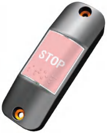
City buses, coaches and BRT vehicles need a "next-stop request" signalling path from any passenger seat to the driver. The traditional wired approach runs a hard-wired button cable from every passenger seat back to a centralised input pin on the cluster — doable on a small vehicle but quickly becomes a harness-routing nightmare on a 12-metre coach with 50+ seats spread across two decks. The wireless approach pairs an in-cabin transmitter button at every signalling location with a single receiver near the driver — one cable from the receiver to the cluster, no wiring back to every seat.
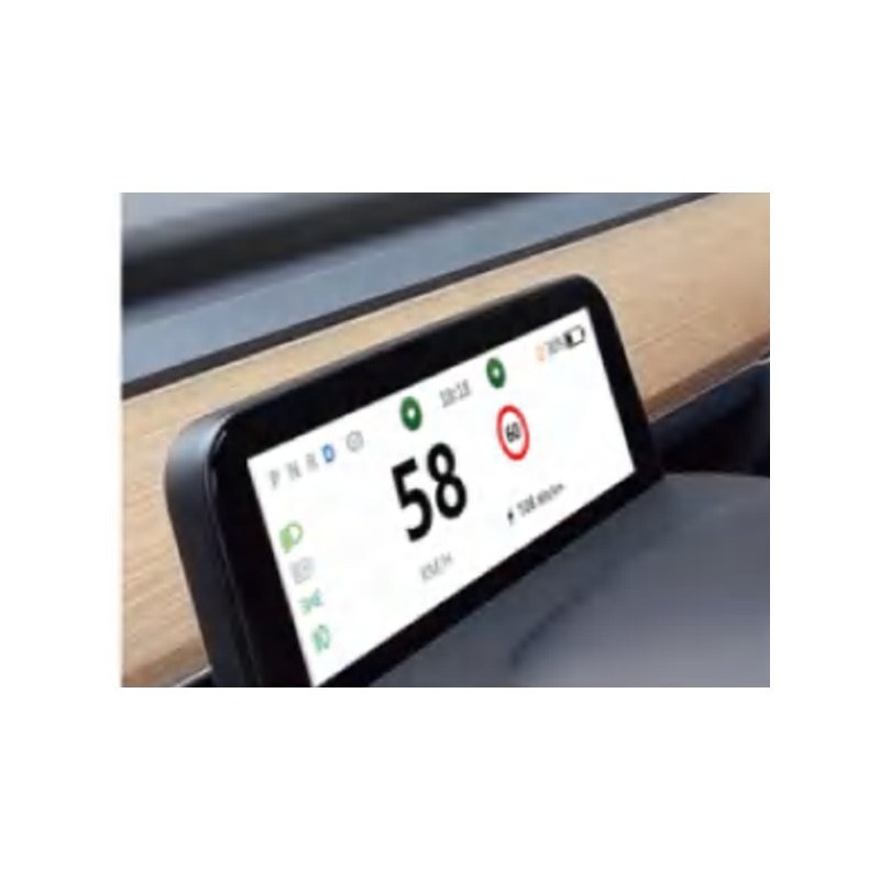
The EBX-2404 implements this pattern with a dedicated twist for the modern accessibility-mandated bus programme: two separate output channels on the connector face. The general stop-request channel (pin 4) carries the standard passenger-press signal — the cluster / annunciator system shows the "next-stop" indicator and sounds the chime. The dedicated disability-accessibility channel (pin 3) carries the wheelchair-ramp / accessibility-stop signal — a separate button placed in the accessibility seat / priority-seat area, which the vehicle programme can act on differently from a routine stop — for example a longer dwell at the next stop, an extended wheelchair-ramp deploy time, or an accessibility-priority annunciation from the driver-side speaker. The two channels are independent low-active outputs — the upstream cluster subscribes to each channel separately and dispatches the corresponding behaviour.
Functional sequence
1. Pairing a new transmitter button
To pair a new wireless transmitter button with the receiver:
- Press the on-board learn button on the receiver once — the run-state LED turns steady-on, indicating that the receiver is now in pairing mode
- Press the new transmitter button once — the receiver captures the new button's wireless ID and adds it to the paired-button list (up to 16 buttons total)
- On successful pairing, the receiver's LED flashes 250 ms on / 250 ms off as the pair-confirmation indication, then returns to steady-off (waiting for the next pairing event)
- Repeat steps 2–3 for each additional transmitter button (up to 16 total)
2. Exiting pairing mode
The receiver exits pairing mode under two conditions:
- Time-out: No transmitter button is paired within 30 s of entering pairing mode — auto-exit
- Manual: Press the on-board learn button again while in pairing mode — immediate exit (useful when the operator has finished a partial pairing run and wants to leave the rest of the buttons for a later session)
3. Clearing all paired buttons
Long-press the on-board learn button for > 3 seconds — the receiver clears all 16 paired-button records and returns to the un-paired baseline. Useful for fleet redeployment / handover or when the fleet operator wants to re-provision a vehicle with a new set of transmitter buttons.
4. Press handling — general stop-request channel (pin 4)
When the receiver demodulates a press signal from any of the paired general transmitter buttons, it asserts pin 4 (general stop-request output) low for the configured pulse width. The upstream cluster / annunciator subscribes to pin 4 and dispatches the "next-stop" indication + chime. After the first signal, the receiver ignores all incoming signals for 1 second — this is the debounce window that prevents a rapid double-press, a near-simultaneous press from two passengers or a momentary RF reflection from chaining multiple stop-requests through the cluster. After 1 s, the receiver returns to normal listening.
5. Press handling — disability-accessibility channel (pin 3)
The dedicated disability-accessibility channel works the same way as the general channel but on pin 3 and on a different paired-button subset (per the fleet's accessibility-button provisioning). When the receiver demodulates a press signal from a paired accessibility transmitter button, it asserts pin 3 (disability-accessibility output) low. The upstream cluster dispatches the "accessibility next-stop" behaviour — longer dwell at the next stop, extended wheelchair-ramp deploy time, accessibility-priority annunciation. The same 1-second debounce applies after the first accessibility signal.
Engineering details
- Two separate output channels — the dedicated disability-accessibility channel separates the standard stop-request from the wheelchair-ramp signal, letting the cluster / annunciator differentiate the two press types and dispatch the appropriate dwell + ramp behaviour
- Up to 16 paired transmitter buttons on a single receiver — sized for a typical 12-metre city bus or a touring coach with multiple stop-request locations spread across the cabin
- Wide 9-36 VDC supply — the same receiver SKU is usable on 12 V (smaller minibus / shuttle) and 24 V (city bus / coach) platforms without a separate part number
- ESD level 4 / class A — cabin-side mounting near passenger contact surfaces; ESD immunity at the level needed for the typical passenger-touch ESD environment
- 1-second debounce after first signal — prevents repeated near-simultaneous presses from chaining unwanted multiple stop-requests; returns to normal listening after the window
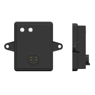
- On-board learn button + 2-LED status — pairing without any external tool, with clear pair-state and run-state visual indication
- IP5K2 baseline / IP65 with optional sealing gasket — cabin-side baseline is the IP5K2 dust-protected splash-protected class; for under-dash / wet-zone placement near windscreen-wash spillage, specify the optional sealing-gasket variant at quotation
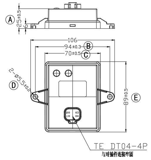
- TE Deutsch DT04-4P / DT06-4S connector pair — industry-standard automotive 4-pin sealed connector with wide global availability for the matching wire-side housing, terminals and seals
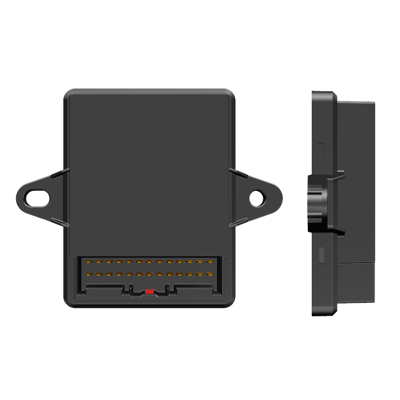
- Compact 106 × 89 × 25 mm body — takes a small footprint on the driver-side bracket above the dashboard
Mechanical layout
4-pin pin-out reference
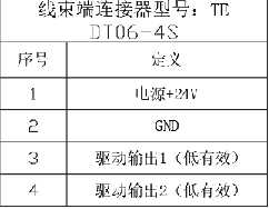
| Pin | Definition | Direction | Level |
|---|---|---|---|
| 1 | Power input +24 V (also accepts the full 9–36 VDC range) | Input | Power |
| 2 | GND | — | GND |
| 3 | Drive output 1 — dedicated disability-accessibility channel | Output | Low-active |
| 4 | Drive output 2 — general stop-request channel | Output | Low-active |
Comparison with related EBX-family wireless receivers
| Model | Domain | Receive band | Output scope |
|---|---|---|---|
| EBX-2404 | Bus stop-request + accessibility | Receiver (programme-specific RF) | 2 low-active digital outputs (general + disability) |
| EBX-957 | TPMS (tyre pressure) | 433.92 MHz frequency-hopping | CAN-published per-wheel pressure / temperature |
| EBX-964 | PEPS (passive entry) | 433.92 MHz ASK | ESCL / start-button CAN gating |
The EBX-2404 is the right choice for a bus / coach programme that wants the passenger-stop-request feature delivered as a wireless cabin-side receiver paired with multiple transmitter buttons, with the accessibility press signal carried on a separate output channel for cluster-side differentiation. For tyre-pressure monitoring with a wireless receiver, look at EBX-957 TPMS receiver; for the wireless passive-entry / push-start function, look at EBX-964 PEPS core controller.
Manufacturing & testing
Built under IATF 16949 with APQP project planning and a PPAP package available for OEM programmes. Every unit is end-of-line functional-tested before packaging — the pair-mode entry / exit / time-out cycle with the LED status profile, paired-button press detection on both pin 3 and pin 4 channels, the 1-second post-press debounce window and the long-press > 3 s clear-all behaviour. ESD class A immunity and the IP5K2 sealing baseline are qualified by type and sample testing rather than on every unit. The optional sealing-gasket variant adds a leak-test step before packaging.
How to ask
The EBX-2404 belongs to the Smart Control Modules family. To request the harness drawing, the wireless-button transmitter SKU, the fleet-provisioning pairing toolchain, the sealing-gasket variant for IP65 placement or a PPAP package, please use the contact page with your target vehicle programme, expected annual volume and key technical requirements (bus / coach platform voltage, transmitter-button count, accessibility-button location, mounting position, IP rating). Drawings welcome. For how the whole stop-request signal chain fits together — wired versus wireless and how a press reaches the driver — see the bus stop request button buyer guide.