Overview
PEPS — Passive Entry Passive Start — is the keyless customer-facing feature familiar from premium passenger vehicles: the driver carries the smart-key fob in a pocket, walks up to the car and the doors unlock automatically when the door handle is touched; the driver sits down, presses the start button and the engine starts without ever taking the fob out of the pocket. The same feature is increasingly specified on premium-trim commercial vehicles and on bus / coach programmes, particularly on the Chinese OEM 24 V commercial-vehicle sector where the trim differentiation matters at the dealer level.
Delivering the PEPS feature on a vehicle programme needs five things to work together: (1) the door-side LF antenna at every door that challenges the fob with a 125 kHz burst, (2) the smart-key fob that listens for the LF burst and responds with a 433 MHz RF burst, (3) the cabin-side RF receiver and central RF demodulator, (4) the ESCL (electronic steering-column lock) that physically gates engine-start authorisation, and (5) the push-button start stack with the brake / clutch interlock. The EBX-964 is the central PEPS controller that orchestrates all five — the door-side antennas, the fob-response demodulator, the ESCL drive interface, the push-button stack and the body-BCM CAN integration are all owned on this single ECU.
For how passive entry, in-cabin localisation and push-to-start work across the wider keyless stack — and how RKE, PKE and full PEPS differ — see the PEPS keyless entry guide; this page stays focused on the EBX-964 controller itself.
PEPS sequence walk-through
1. Passive entry — driver walks up to the door
When the driver touches the door handle (or pulls the handle), the door-handle sense input on the body-BCM triggers a PEPS challenge on the corresponding door's LF antenna. The EBX-964 drives a 125 kHz ASK-modulated challenge burst out of the matching differential antenna pair (DRV1+/− for door 1, DRV2+/− for door 2, etc.). The challenge encodes the vehicle ID and a session nonce.
The smart-key fob (sold separately) demodulates the 125 kHz challenge, validates the vehicle ID against its paired ID, and broadcasts a 433.92 MHz response burst back with the coded authentication payload. The EBX-964's RF demodulator captures the burst and authenticates against the paired key set; on authentication-pass, the controller publishes a "door-unlock permitted" message onto CAN, and the body BCM drives the corresponding door-lock motor.
2. In-cabin localisation — driver sits down
Once the driver is seated, the EBX-964 runs an in-cabin challenge using a combination of the four LF antennas to locate the fob position. If the fob is detected inside the cabin (and not, e.g., outside the driver-door window), the controller publishes a "fob-in-cabin" state onto CAN.
3. Push-to-start — driver presses the start button
With the fob-in-cabin state asserted, the brake or clutch pedal pressed (the interlock input) and the gear-position switch in N or P, a press on the START button input drives the firmware's one-button-start sequencer. The sequencer commands the ESCL to unlock (gating the engine start), drives the ACC output high, waits the program-defined dwell, drives the IGN output high, waits the program-defined dwell, drives the START output high to crank the engine, and releases START on engine-running confirmation from the body-BCM. A second press (with the engine running) commands engine-stop via the EG2 input + the ACC / IGN release sequence + the ESCL re-lock.
4. Passive exit — driver walks away
When the driver exits the vehicle (door-open / door-close cycle on a door whose paired fob is on the driver side), the EBX-964 runs a final in-cabin challenge; if no paired fob is detected inside the cabin, the controller publishes a "fob-departed" state and the body BCM locks the doors. If the fob is still detected inside the cabin, the controller withholds the lock command and triggers the "key-left-in-cabin" warning over CAN.
Engineering details
- 4 differential LF antenna driver pairs — one pair per door; the differential drive gives a clean 125 kHz waveform without ground-loop noise, which is critical for the localisation algorithm to distinguish "outside door 1" from "outside door 2" from "inside cabin"
- ASK modulation on both the LF challenge path and the RF response path — standard for the automotive PEPS sector, fob-side parts widely available from the leading semiconductor vendors
- Dedicated ESCL interface with wake / power / LIN to the external ESCL motor unit — the ESCL physically locks the steering column when the controller commands lock, providing the physical anti-theft / start-gating function that the security policy requires
- One-button-start firmware sequencer with brake / clutch interlock — the sequencer enforces the program-specific start-permission policy (gear-in-N-or-P, brake-pressed, fob-in-cabin, ESCL-unlocked, all checks pass) before driving the START output
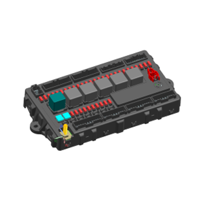
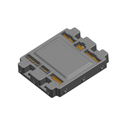
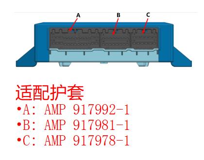
- Three-connector harness face (AMP 917992-1 + 917981-1 + 917978-1) — harness designer cleanly separates the LF antenna drive side (connector C) from the ESCL / RF / sense side (connector A) from the push-button stack / interlock / CAN side (connector B); the LF antenna pairs run on shielded twisted-pair from connector C to the door-side antennas, which keeps the 125 kHz signal clean over the cab-side harness length
- Pairing learn-mode on the standard build — the program can pair a new smart-key fob via the controller's learning sequence (typically triggered from the body-BCM diagnostic tool or from a service-mode CAN command), without needing an external PEPS-specific programmer
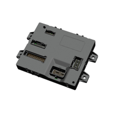
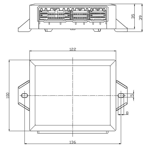
- Free-orientation mounting; IP53 sealing class suitable for behind-dash placement
Mechanical layout
Three-connector harness face (AMP)
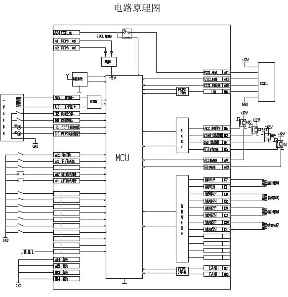
PEPS-system block diagram (reference schematic)
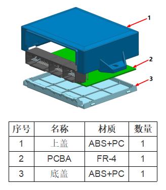
Construction
PEPS ecosystem partners (sold separately)
| Component | Role in the PEPS system |
|---|---|
| EBX-964 (this module) | Central PEPS controller — orchestrates LF challenge, RF response, ESCL gating, push-start sequencer |
| EDK-911 electronic steering-column lock (see switches & sensors) | Physical anti-theft lock on the steering column; gated by the PEPS controller |
| TDK-902 one-button-start switch (see switches & sensors) | The push-start button on the dashboard — input to the PEPS sequencer |
| Smart-key fob (programme-specific) | The fob the driver carries; receives 125 kHz LF challenges and responds at 433.92 MHz |
| LF antenna modules (4 ×, programme-specific) | Door-side / cabin-side LF antennas driven by the EBX-964's four differential pairs |
| Gear-position switch (programme-specific) | N / P interlock input to the PEPS start sequencer |
The EBX-964 is the central PEPS controller. The other five components are sold separately and confirmed against the programme's PEPS specification at quotation. A complete PEPS system needs one EBX-964 plus the matching smart-key fob, one EDK-911 ESCL, one TDK-902 start button (or programme equivalent), four LF antennas (typically one per door) and a gear-position switch.
Comparison with other Youlai PEPS-capable BCMs
| Model | Pattern | PEPS | System |
|---|---|---|---|
| EBX-964 | Dedicated PEPS core controller | Yes (full PEPS, 4 × LF antenna pairs) | 24 V (18–32 VDC) |
| EBX-2169 | 178-pin full-scope BCM with integrated PEPS | Yes (PEPS as a subset of the BCM) | 12 V (9–16 VDC) |
| EBX-2305 | New-energy BCM with PKE (RKE + smart-key) | Subset (PKE not full PEPS sequencer) | 12 V (9–16 VDC) |
The EBX-964 is the right choice for a 24 V commercial-vehicle programme that wants the PEPS feature on a dedicated standalone controller — particularly when the program's main BCM is a pure-logic / fuse-relay-integrated BCM (e.g. EBX-953 / EBX-954) without a PEPS sub-system on board. For a 12 V programme that wants PEPS as a subset of a full-scope BCM, look at EBX-2169 (integrated PEPS on a 178-pin BCM).
Manufacturing & testing
Built under IATF 16949 with APQP project planning and a PPAP package available for OEM programmes. Every unit is end-of-line functional-tested before packaging — the 4 LF antenna differential driver pairs (each measured for 125 kHz output amplitude and waveform integrity), the 433.92 MHz RF demodulator with a paired test fob, the ESCL interface handshake, the ACC / IGN / START push-button sequencer with simulated brake / clutch / gear-position inputs, the CAN bus health, and the +5 V internal supply rail are all checked. EMC pre-compliance screening in our in-house lab follows the OEM EMC profile.
How to ask
The EBX-964 belongs to the Smart Control Modules family. To request the harness drawing, the PEPS specification, the per-pin allocation across the three AMP connectors, the LF antenna driver tuning option, the RF-receive sensitivity profile, the ESCL-vendor compatibility list, the pairing toolchain or a PPAP package, please use the contact page with your target vehicle programme, expected annual volume and key technical requirements (door count + cabin layout for the LF antenna count, ESCL vendor + lock-motor specification, smart-key fob vendor + crypto profile, push-start button model, CAN protocol, IP rating, connector preference). Drawings welcome.