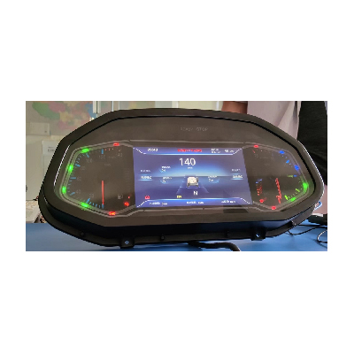
Overview — the plateau-grade combined cluster
Mainstream Chinese-market truck clusters are rated to roughly −30 °C ambient and 4000 m altitude, which covers most heavy-truck operating territory but fails the corner cases that define some of the most valuable Chinese commercial-vehicle programmes — the Tibet plateau heavy-truck route (5000 m mountain passes, sub-−40 °C winter night-stops on the Qinghai-Tibet line), the high-altitude mining sector (Tibet copper, Qinghai potash, Xinjiang gold, Inner Mongolia rare-earth all routinely operate above 4500 m altitude), and the winter long-haul corridors of north-east China and Heilongjiang where ambient temperature drops below −40 °C for weeks at a time.
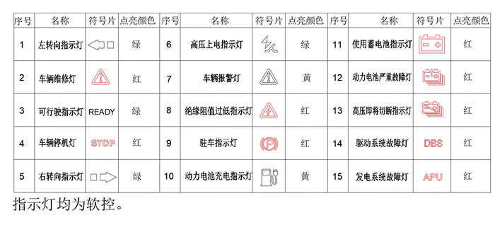
The PBX-2301 is the plateau-grade cluster built for exactly these scenarios. 5000 m altitude rating, −45 °C ambient operation with built-in low-temperature self-heating, salt-spray ≥ 100 h (matching the winter-road de-icing-salt exposure on the plateau routes) and damp-heat ≥ 240 h. The same body family extends into the new-energy heavy-truck market on the strength of its 9 dedicated EV indicator LEDs — READY, STOP, HV power-up, insulation-resistance low, battery charging, severe battery fault, imminent HV cut-off, DBS drive-system fault and APU generator fault all software-driven directly from the BMS / VCU messages on the CAN bus.
Engineering details
Low-temperature self-heating
An LCD panel without active heating typically fails to start at temperatures below roughly −25 °C — the liquid-crystal viscosity rises sharply, the panel goes ghosting / slow-response and the start-up sequence can stall on the initial calibration step. The PBX-2301 carries a built-in heater element behind the display, controlled by the cluster's own MCU based on the internal temperature reading. On cold-start the heater runs at the higher 20 W envelope until the panel reaches normal display state, then drops back to the steady 10 W normal-operation envelope. The operator sees a normally-rendered display from the first instant the cluster is powered up, with no "cold-screen waiting" period.
9 dedicated new-energy / EV indicators
The cluster carries 15 LED indicators in total. Six are the conventional commercial-vehicle markers (turn signals L/R, vehicle service warning, parking-brake, generic vehicle warning, auxiliary 24V battery in-use). The other nine are dedicated to electric / hybrid drivetrains:
- READY (green) — vehicle is in drive-ready state after HV power-up sequence completes
- STOP (red) — vehicle has stopped HV operation, must be re-cycled to re-enter ready state
- HV power-up indicator (green) — the high-voltage traction-pack contactors have closed and the bus is energised
- Insulation-resistance low (red) — the on-board isolation monitor has detected a leakage path on the HV bus, vehicle should be de-energised and serviced
- Traction-battery charging (yellow) — pack is charging from an external source
- Traction-battery severe fault (red) — BMS has reported a severe pack-level fault
- HV imminent cut-off (red) — the BMS / VCU is about to open the contactors due to a safety-critical condition
- DBS drive-system fault (red) — the drive-by-wire / brake-by-wire system has reported a fault condition
- APU generator fault (red) — the auxiliary power unit (range-extender / hybrid generator) has reported a fault
All 15 indicators are software-controlled (no fixed-wired indicator lines), so the OEM can adjust the indicator-to-CAN-message mapping per programme without hardware changes.
Dual-CAN with CAN-FD support
Both CAN channels run at 500 kbps with CAN-FD (Flexible Data-rate) support — an important capability on a 2024-class commercial-vehicle cluster, because CAN-FD carries up to 64 bytes per frame (versus 8 bytes for classic CAN) and reaches up to 5 Mbps data-phase rate. CAN-FD lets the cluster receive richer telemetry frames (BMS cell-by-cell voltage / temperature, multi-channel diagnostic packets) without the frame-fragmentation overhead that classic CAN imposes. The primary "info" CAN bus carries the standard vehicle telemetry; the secondary "reserved" CAN bus is available for programme-specific second-bus integration (a dedicated BMS bus, a private diagnostic bus, or a peripheral-display chain).
Dual AV video input — infrared night-vision + reverse camera
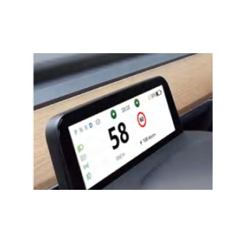
Both AV inputs (AV1 + AV2) on the PBX-2301 are full-function video paths with switched 24 V / 50 W supply on the camera side. AV1 is wired for the infrared night-vision sensor (typical placement on heavy-truck cabs operating in winter night-stop or off-road scenarios), AV2 is wired for the reverse camera with a reverse-signal-output line that the cluster drives back to the camera to wake it up only when reverse gear is engaged. Both video channels render on the centre 8" IPS display, with the cluster's HMI logic deciding the active video source based on the vehicle state.
XCB main connector + dual GX12M AV connectors
The rear connector arrangement keeps the high-pin-count main interface (XCB30F30Z1D1, 30 pins, AVIC Optoelectronics XC commercial-vehicle series) physically separate from the two video interfaces (each on a small 4-pin GX12M-F-4 circular connector). The advantage at integration time is that the OEM-side cab harness can route the main wiring loom to the cluster on one path, and the two camera coaxials on a second path without the bulk and routing complexity that combining all three onto a single connector would create. The XC commercial-vehicle series is qualified for the cab vibration envelope and is the same connector family used across the rest of the Youlai commercial-vehicle cluster product line.
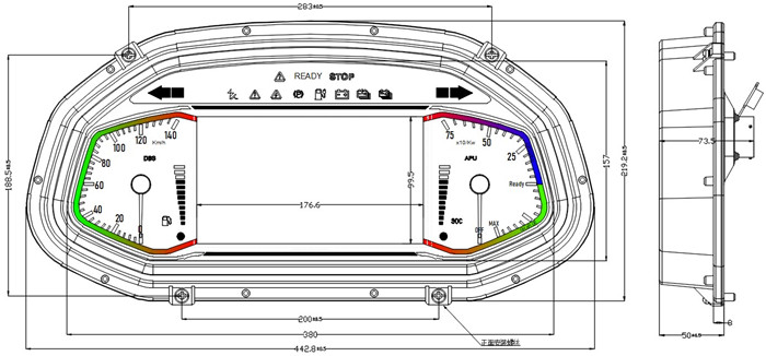
Display layout — twin analogue dials + 8" IPS centre
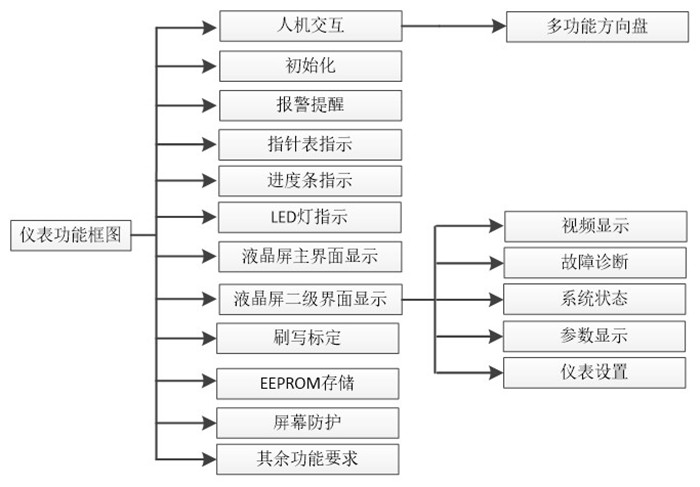
Function block diagram
Rear connector face — 30-pin main + dual AV
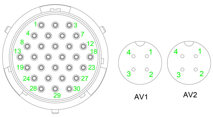
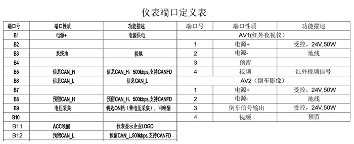
Pin-out table — main connector + AV connectors
Indicator LED reference (15 total — 9 EV-specific)
Comparison with the rest of the Youlai cluster line
| Model | Display | Working temp. | Altitude | EV-specific markers | Position in the line |
|---|---|---|---|---|---|
| PBX-2202 | 4.6" IPS 960×320 | −40 to +85 °C | Standard | No | Mid-range smart cluster, broad heavy-truck deployment |
| PBX-2301 | 8" IPS 1080×720 | −45 to +75 °C (self-heating) | ≥ 5000 m | 9 dedicated EV LEDs | Plateau / new-energy heavy-truck cluster |
The PBX-2301 is the right choice for any heavy-truck programme deploying into plateau / high-altitude territory (Tibet, Qinghai, plateau-mining sectors), any extreme-cold long-haul route (north-east China / Heilongjiang / cross-border Russia / cross-border Kazakhstan winter operations) and any new-energy commercial-vehicle programme needing dedicated EV indicators wired through to the BMS / VCU. For more conventional heavy-truck cabin programmes that do not need the plateau / cold envelope, look at PBX-2202 — the same engineering family but lighter on the environmental qualification.
Manufacturing & testing
Built under IATF 16949 with APQP project planning and a PPAP package available for OEM programmes. Every unit is end-of-line functional-tested before packaging — the 8" IPS display panel calibration, the dial pointer drive across the full range, all 15 LED indicators driven from the firmware, the self-test cycle completion under 2 seconds, both CAN channels running with the configured baudrate and CAN-FD mode, both AV inputs accepting test pattern and rendering on screen, the rear connector pin-continuity, the low-temperature self-heating function (verified on the cold-environment test bench) and the salt-spray + damp-heat aged samples on a per-batch basis. The QC/T 413 reference standard validation is run on first-article samples and on periodic batch-audit cycles.
How to ask
The PBX-2301 belongs to the Displays & HUD family. To request the dial-face artwork specification (speed range, brand styling, dial graphics layer), the indicator-icon mapping (which of the 15 LEDs maps to which CAN message), the CAN-FD baudrate / message-ID layout, the rear-harness drawing or a PPAP package, please use the contact page with your target vehicle programme, expected annual volume, deployment territory (especially the altitude and cold-climate envelope) and key technical requirements (analogue dial range, EV indicator mapping, AV video specification, mounting cut-out). Drawings welcome.