Overview — a hardwired bidirectional motor-drive stage
Most of the smart controllers in the EBX family are high-side-driver (HSD) modules: they switch a load on or off from the positive rail, and they take their commands over a CAN bus from the vehicle's body-control network. That pattern is perfect for lamps, solenoids and accessory loads that only need to be turned on and off. It is the wrong tool for a load that has to run both directions — a flap that opens and closes, a damper that rotates one way then the other, a small positioning motor that has to reverse.
The EBX-951 is built for exactly that job. Each of its eight motor channels is a full H-bridge, so each channel can drive its DC motor forwards or backwards. Seven of the eight channels add PWM speed control, so the motor speed (or the actuator's approach rate) is set by duty cycle rather than being all-or-nothing, and each channel senses its own current so the load on each motor is visible to whatever logic drives the inputs. The eighth channel is a higher-current 10 A H-bridge for the one actuator on the harness that draws more than the 5 A channels can supply.
The EBX-951 is also hardwired rather than bus-attached: it takes its commands and its feedback through 4 digital inputs and 8 analog inputs wired directly to the switches, position pots and sensors around it, not over CAN. That makes it a self-contained motor-drive stage that can sit downstream of a main controller (or be driven directly by cab switches and feedback sensors) without needing a place on the vehicle's CAN message map. Where the smart-logic decisions live — and how a bus-attached body controller differs from a driver stage like this — is covered in the BCM vs VCU vs PMU comparison.
I/O capability set
8 × H-bridge motor drives (bidirectional)
The eight H-bridge channels are the core of the module. Seven channels are rated 5 A and carry the full feature set: PWM speed control with a duty cycle from 0 to 100% and an adjustable PWM frequency from 10 Hz to 2 kHz, per-channel current sensing with a 6 A feedback range, and a built-in freewheeling diode to absorb the inductive kick when an inductive motor load is switched. The eighth channel is rated 10 A with current sensing but no PWM — it is intended for the highest-current actuator on the harness that needs forward/reverse rather than speed modulation. Because every channel is a bridge, every channel drives its motor in both directions; PWM speed control is available on the seven 5 A channels, while drive direction is set per channel.
4 × digital inputs (DI)
The four digital inputs are active-high with a configurable threshold and a 4.7 kΩ input impedance. They absorb the command switches and the discrete feedback around the module — a raise/lower rocker, an end-of-travel limit switch, an enable / interlock line.
8 × analog inputs (AI)
The eight analog inputs sample continuously (real-time data) with a configurable upper and lower threshold per channel and a high ≥ 100 kΩ input impedance so they load the sensor lightly. They are the module's feedback path — typically position potentiometers on the actuators, or pressure / temperature sensors whose value the driving logic compares against the configured thresholds. The exact analog input range is set per programme on the harness drawing.
Three-stage supply-voltage protection
A dedicated supply-voltage state machine guards the whole driver bank against the wide, noisy voltage a commercial-vehicle 24 V rail actually delivers, and reports its state on a red fault LED:
- Normal (18 – 32 V) — the red fault LED is off; all channels drive normally.
- Under-voltage alarm — when the supply Us falls below 18 V for 1 s, the module raises an under-voltage warning and the red LED slow-blinks at 1 Hz.
- Under-voltage cut-off — when Us falls below 9 V for 0.5 s, the module enters under-voltage protection (the drivers are cut to protect the motors and the bridge) and the red LED fast-blinks at 5 Hz.
- Over-voltage shutdown — when Us rises above 32 V for 0.5 s, the module enters over-voltage protection and the red LED goes steady on.
Engineering details
- Bidirectional by design — eight H-bridge channels, so every driven motor can run forwards and backwards; this is the fundamental difference from the HSD (high-side switch) modules in the family, which can only turn a load on and off.
- PWM speed control on 7 channels — 0–100% duty cycle, 10 Hz–2 kHz adjustable frequency, so actuator approach rate and motor speed are tunable per channel rather than fixed.
- Per-channel current sensing — 6 A feedback range on the seven 5 A channels; each channel reports how much current its motor is drawing, so the logic driving the inputs has per-motor load visibility to work with; how that reading is used (stall detection, end-of-travel, over-current cut) is defined for each programme.
- Built-in freewheeling diodes on the 5 A channels — the inductive fly-back from a switched DC motor is absorbed on-board rather than being thrown back onto the harness.
- Hardwired command + feedback — 4 DI + 8 AI wired directly to switches and sensors; the module works without a seat on the vehicle CAN message map, which keeps it usable as a standalone driver stage or a downstream driver under a main controller.
- Three-stage voltage protection with fault LED — under-voltage alarm, under-voltage cut-off and over-voltage shutdown guard the bridge bank on a real-world 24 V rail, with the state shown on the red fault LED for quick field diagnosis.
- IP67 sealed, −40 to +85 °C — dust-tight and protected against temporary immersion, so it can mount outside the protected cabin; final placement and sealing are confirmed per programme.
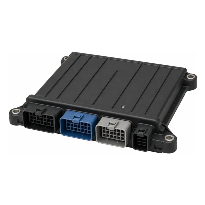
- Four TE sealed connectors — three 23-pin connectors (Black / Blue / Natural) plus one 8-pin connector, colour-coded so the three 23-pin bodies are easy to tell apart on the harness.
Technical reference (connector P/Ns)
| Position | Connector | Colour | Harness-side P/N (TE) | Board-side P/N (TE) |
|---|---|---|---|---|
| A | 23-pin | Black | 776200-1 | 770680-1 |
| B | 23-pin | Blue | 776200-5 | 770680-5 |
| C | 23-pin | Natural | 776200-2 | 770680-2 |
| D | 8-pin | Black | 776275-1 | 776286-1 |
Per-pin allocation (which I/O lands on which cavity) is issued against the customer harness drawing at quotation. The three 23-pin bodies are colour-coded (Black / Blue / Natural) to keep them easy to identify on the harness.
Comparison with the related Youlai control modules
| Model | Drive type | Command path | I/O scope | IP grade |
|---|---|---|---|---|
| EBX-951 | 8 × H-bridge (bidirectional) 1×10A + 7×5A PWM | Hardwired (4 DI + 8 AI) | 20 (4 DI + 8 AI + 8 drives) | IP67 |
| EBX-962 | 8 × HSD-PWM (on/off, high-side) | CAN-attached | 8 HSD + 4 DI/AI + 2 INT + CAN | IP65 |
| EBX-2050 | 12 × HSD-PWM + integrated fuse/relay box | SAE J1939 CAN | 12 PWM + 17 DI + 24 DOH | IP54 |
| EBX-963 | Body-function drives (top-cover / tail-gate / lift / PTO) | CAN + RF key + APP | Dump-body function set | IP53 |
Choose the EBX-951 when the loads are bidirectional DC motors that need speed control and current feedback, driven from local signals. For an on/off high-side accessory extension on the CAN bus, look at the EBX-962 I/O expansion module; for a combined smart-logic plus power-distribution box with 12 PWM channels and J1939 diagnostics, look at the EBX-2050 integrated PMU; for a turnkey dump-truck body controller with the actuator logic already written, look at the EBX-963. If the drive stage is still being scoped — whether the load reverses at all, how many channels the duty cycle really needs, and what stall current does to a rating written for running current — the DC motor & actuator control guide works through that decision before the model choice.
Manufacturing & testing
Built under IATF 16949 with APQP project planning and a PPAP package available for OEM programmes. Units are end-of-line functional-tested across the drive channels, the digital and analog inputs and the supply-voltage protection behaviour before packaging. EMC pre-compliance screening is run in our in-house lab; the programme-specific EMC profile, together with the vibration, sealing and service-life targets, is confirmed at quotation.
Selection questions
Does the EBX-951 use a CAN or LIN bus?
Its published specification does not list a CAN or LIN interface — the EBX-951 is hardwired. Commands and feedback come in through 4 digital inputs and 8 analog inputs wired directly to switches and sensors. If your architecture needs a CAN / J1939 module, the EBX-962 I/O expansion and the EBX-2050 integrated PMU are the bus-attached alternatives.
Are the 5 A and 10 A ratings continuous, and can all eight channels run at once?
They are the per-channel drive ratings. Whether all eight run simultaneously, and any thermal derating, depend on your duty cycle and ambient temperature — send the motor list with each motor's running and stall current and we confirm the safe channel allocation for your programme.
Which motors and actuators does it suit?
Brushed DC motors and actuators — window, flap, damper, louvre and valve actuators, and pumps that have to run in both directions. Because each channel is a bidirectional H-bridge, it handles loads that reverse; a load that only ever runs one way does not need a bridge and is better served by a high-side channel. Specify each motor's running current and its stall current so the 5 A versus 10 A allocation is set correctly.
How to ask
The EBX-951 belongs to the Smart Control Modules family. To request the harness drawing, the per-connector pin allocation, the mechanical drawing or a PPAP package, please use the contact page with your target vehicle programme, expected annual volume and key technical requirements (number of bidirectional motors + per-motor running / stall current, which channels need PWM speed control, the analog feedback sensor list, IP rating and connector preference). Drawings welcome.