Overview
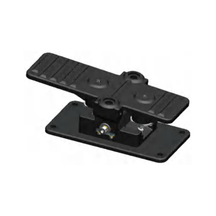
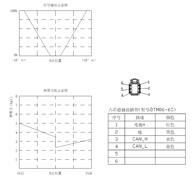
A travel pedal is how the operator of a self-propelled machine commands it to move. The TDK-2408 is Youlai's bidirectional version of that control: a rugged foot pedal that rocks ±16° fore and aft from centre and reports a published position signal over CAN — 0% at centre, rising to 100% at either end stop. What still gets confirmed with the machine builder is how that position signal is packed on the bus (message ID, baud rate) and how the travel controller reads fore versus aft, not the position curve itself.
What sets it apart from the momentary rocker and push-button switches elsewhere in the cab is that the operator works it under load for a whole shift, and it talks to the controller over the bus. So the two things worth reading on its datasheet are the CAN fault behaviour and the force figures — not a simple on/off contact rating.
What happens on a fault
One fault behaviour is worth calling out on its own. If a fault is detected at any pedal position, the CAN travel data auto-zeros — the pedal reports zero travel instead of leaving a stale "keep moving" value on the bus, so the machine controller sees a request to stop. Where your programme runs a formal functional-safety assessment, tell us the target level and the controller it talks to, and the pedal and its signal chain get specified against that rather than assumed.
Force figures, and what they mean
The pedal is defined by three forces rather than a vague "feel": 5.5 N to break away from centre, 17.8 N to reach full deflection, and a 300 N maximum allowable force at the end stop. Read together they describe the whole stroke — how deliberate the first movement is, how tiring a long shift will be at full travel, and how much mechanical margin the pedal keeps before anything is at risk. The ±16° of fore/aft travel is the mechanical range the published 0–100% position curve is drawn across.
Connector & pinout
The TDK-2408 uses a six-pin Deutsch DTM06-6S. The published pin map is:
- Pin 1 — Power+ (red)
- Pin 2 — GND (black)
- Pin 3 — CAN_H (yellow)
- Pin 4 — CAN_L (blue)
- Pins 5–6 — unused
CAN baud rate and message-ID layout are confirmed per machine programme. Share your travel-controller interface at quotation and we align the build to it.
Dimensions & mounting
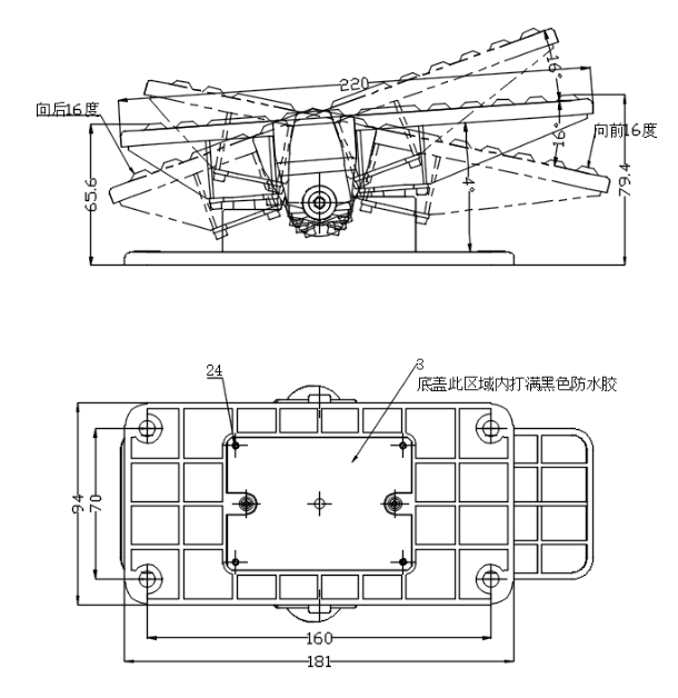
The reference drawing gives a pedal length of 220 mm, a base plate of 181 × 94 mm, and mounting hole centres at 160 × 70 mm. Fore and aft travel are each 16°. The bottom-cover drawing marks a sealed region filled with black waterproof adhesive as part of the IP65 build. Use these as the published footprint for cab-floor layout; tell us if your floor clearance or bolt pattern needs a programme-specific check against that drawing.
Built for the cab floor
The cab floor of a working machine is one of the harsher places to mount an electrical part — mud, water, grit and boots all end up there. The TDK-2408 is sealed to IP65 (IEC 60529: dust-tight, and protected against water jets from a 6.3 mm nozzle — a jets rating, not an immersion one) and qualified from −40 to +85 °C, with −45 to +90 °C storage, for machines that cold-soak overnight and then run hot in the sun. Unspecified dimensions are held to GB/T 1804-2000 MT5 so the mounting footprint stays consistent batch to batch. The 8 – 32 VDC window covers both 12 V and 24 V machines, and the input withstands at least 50 VDC.
What we set with you at RFQ
The connector, pinout, position curve and reference mounting footprint are already published above. What still gets confirmed with you at quotation is how the pedal lands on your machine:
- CAN baud rate and the travel message layout your controller expects;
- how your controller should read fore versus aft from the position signal;
- harness length and any mating-connector preference on the vehicle side;
- cab-floor clearance or bolt-pattern checks against the published 181 × 94 mm footprint;
- mechanical and electrical life targets for the duty cycle;
- vibration, sealing and EMC targets, plus any destination-market approvals.
Sending these up front means the first sample is closer to your machine, not a generic reference build.
Manufacturing & testing
The pedal is built under IATF 16949 with APQP project planning, and a PPAP package is available on programme handover. End-of-line checks and sample-based sealing and endurance validation run to the control plan agreed for each programme, and the resulting reports form part of that PPAP package. Where a design needs fresh validation, environmental and EMC pre-compliance screening runs in our in-house lab, with formal EMC certification handled at accredited third-party laboratories when the programme calls for it.
Common questions
Is it a proportional pedal or an on/off switch? Not a plain contact — the published curve is 0% at centre and 100% at either ±16° end stop, reported over CAN. What still gets confirmed per programme is the CAN message layout and how your controller reads fore versus aft.
What voltage systems does it support? 8 – 32 VDC, so both 12 V and 24 V machines, with the input withstanding at least 50 VDC.
What happens if the pedal fails? The CAN travel data auto-zeros at any position, so the controller reads a stop request rather than a stale command.
Is it sealed enough for the cab floor? The TDK-2408 is sealed to IP65 per IEC 60529 — dust-tight and protected against water jets from a 6.3 mm nozzle, which is a jets rating rather than an immersion one — and qualified from −40 to +85 °C, with −45 to +90 °C storage, for the cab-floor environment.
What do you need to quote it? Machine type, system voltage (12 V or 24 V), your travel-controller CAN message layout and baud rate, harness length, any mounting check against the published 181 × 94 mm footprint, and expected annual volume. Drawings welcome.
How to ask
The TDK-2408 sits in the Switches & Sensors family and is normally specified into a machine build alongside the auxiliary controls on the same body network — the construction-machinery electronics overview shows where a travel pedal sits between the control layer and the hydraulic output stage. If you want the background on how a CAN body network carries these commands, the CAN bus switch panel buyer guide walks through it. To move on the part itself, use the contact page with the details above and any drawings — we typically reply within one business day.