A general-purpose part in a vehicle catalogue
Most of the parts on this site are built for a vehicle. The YL02-WK is not. Youlai lists the series for temperature control on transformers, engines, integrated circuits and general electrical equipment. Engines put it on commercial vehicles and machinery, which is why it sits in this family, but the same part number is bought for a transformer tank, a rectifier heatsink or a cabinet fan. If you need a switch that is qualified against a specific automotive programme standard, tell us at RFQ and we will confirm what applies rather than assume it.
Functionally it is the simplest device on the site. A sealed probe holds a single thermal protector element. Below its set point it sits in one state; at the set point it changes state; when the temperature falls back to the published reset point it returns. There is no power pin, no electronics and nothing to configure — the two leads are just the two sides of a switch. That is what makes it cheap, and it is also what makes it a threshold device rather than a measurement device: it tells you crossed or not crossed, never the actual temperature. If you need a reading, you need a sender or a sensor, not this.
How to order: the part number is the specification
The series is parametric. Three fields after YL02-WK select the variant — mounting, contact form and set point:
| Field | Code | Meaning |
|---|---|---|
| Mounting | 6 | M10 threaded boss, fixed with lock nuts |
| 8 | Plain probe, fixed with a strap or cable tie | |
| Contact form | A | Normally open — contact closes on rising temperature |
| B | Normally closed — contact opens on rising temperature | |
| Actuation temperature | 3 digits | Set point in °C — 080 = 80 °C, 110 = 110 °C |
So YL02-WK6A110 is a bolt-mounted, normally open switch that closes at 110 °C, and YL02-WK8B080 is a strap-mounted, normally closed switch that opens at 80 °C. Quote the full code and those three choices are unambiguous. What the code does not carry is the harness side — lead length, connector or flying-lead termination, and any bracket — so state those with the code on your first order and they are fixed on the drawing with it.
Two mounting styles
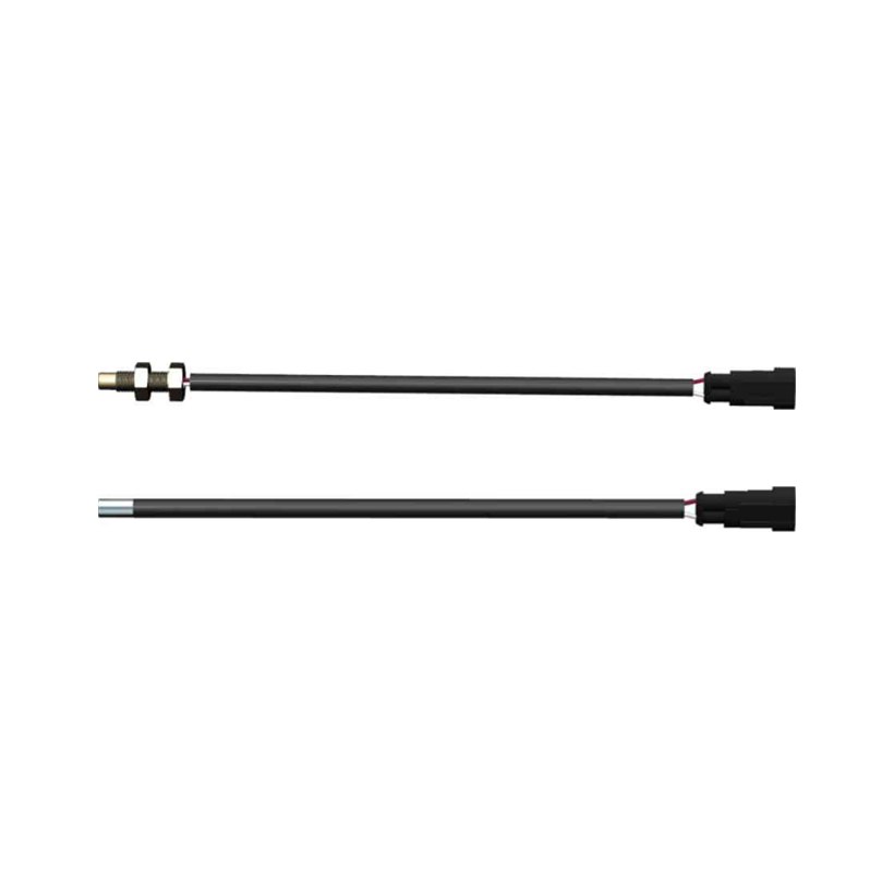
The two variants are the same switch in a different body, so the choice is purely about how the probe reaches the thing you are measuring.
| Variant | Fixing | Suits |
|---|---|---|
| YL02-WK6 | M10 threaded boss with lock nuts | A clearance hole through a bracket, a boss or a housing wall — a repeatable, torqued mechanical interface |
| YL02-WK8 | Plain probe, strapped or cable-tied | Clamping against a pipe, a winding, a heatsink face or a hose where you cannot drill |
Both carry the same lead and the same connector, and the lead length is customizable — worth specifying up front, because it is the one dimension that decides whether the part fits your loom without a splice.
Actuation and reset temperatures
The series covers 26 steps in 5 °C increments. Each step has its own reset temperature, and the gap between the two — the hysteresis — is the number that decides whether the part behaves well in your application. Read the reset column before you pick a step.
| Actuation | Reset | Actuation | Reset |
|---|---|---|---|
| 30 ± 3.5 °C | ≥ 20 °C | 95 ± 5 °C | 70 ± 15 °C |
| 35 ± 4 °C | ≥ 25 °C | 100 ± 5 °C | 70 ± 15 °C |
| 40 ± 4.5 °C | ≥ 30 °C | 105 ± 5 °C | 75 ± 15 °C |
| 45 ± 5 °C | ≥ 33 °C | 110 ± 5 °C | 75 ± 15 °C |
| 50 ± 5 °C | ≥ 35 °C | 115 ± 5 °C | 80 ± 15 °C |
| 55 ± 5 °C | ≥ 40 °C | 120 ± 5 °C | 85 ± 15 °C |
| 60 ± 5 °C | 42 ± 6 °C | 125 ± 5 °C | 85 ± 15 °C |
| 65 ± 5 °C | 45 ± 8 °C | 130 ± 5 °C | 90 ± 15 °C |
| 70 ± 5 °C | 50 ± 12 °C | 135 ± 5 °C | 95 ± 15 °C |
| 75 ± 5 °C | 53 ± 14 °C | 140 ± 5 °C | 100 ± 15 °C |
| 80 ± 5 °C | 55 ± 15 °C | 145 ± 5 °C | 100 ± 15 °C |
| 85 ± 5 °C | 60 ± 15 °C | 150 ± 5 °C | 105 ± 15 °C |
| 90 ± 5 °C | 65 ± 15 °C | 155 ± 5 °C | 110 ± 15 °C |
Two patterns are worth pointing out before you specify. First, the hysteresis widens as the set point rises: a 60 °C part resets around 42 °C, an 18 °C gap, while a 155 °C part resets around 110 °C, a 45 °C gap. If you are switching a cooling fan, that gap is how far the temperature falls before the fan stops — generous hysteresis prevents chatter but means long run-on. Second, the tolerances are real and they stack: a 110 °C step is 105–115 °C on actuation and 60–90 °C on reset, so design your alarm or control threshold against the worst-case corner, not the nominal figure. At the bottom of the range the reset is published as a floor (≥) rather than a band — a 30 °C part resets at 20 °C or above, so the hysteresis there is capped at about 10 °C rather than guaranteed to be it.
The ambient the switch itself may sit in is published as −30 °C up to 50 °C above its actuation temperature, so a 110 °C part is rated to see about 160 °C around it. Storage is −40 to +90 °C. If your installation runs the probe close to that upper bound continuously, confirm the specific variant with us rather than reading it off the series sheet.
Contact rating and wiring
The switch terminates in a two-way connector whose harness side is an AMP 282080-1. Both cavities are simply the two sides of the contact — the drawing labels them switch output 1 and switch output 2 — so there is no supply pin, no ground pin and no polarity to get wrong.
| Item | Detail |
|---|---|
| Mating connector | AMP 282080-1 |
| Cavity 1 | Switch output 1 |
| Cavity 2 | Switch output 2 |
| Rated current | 4 A @ 12 V · 3 A @ 24 V |
| Polarity | None — dry contact |
At 4 A / 12 V or 3 A / 24 V the contact suits a relay coil, a warning lamp or a controller input directly; it is not sized for a cooling fan or a heater. One thing to note when you size it: the figure is published as a bare current rating with no load category attached, so for an inductive load — and a relay coil is one — the thing that shortens contact life is the arc drawn when the circuit breaks, not the steady current. Put the suppression on your side (a flyback diode across a DC coil, or an RC snubber), or send us the load at RFQ and we will confirm it against the contact set. If the load is larger than the rating, switch a relay with it, or feed it as an input to a body controller or a power distribution box and let the output stage carry the current — which is also how you get the over-temperature condition onto the vehicle network instead of leaving it as a local circuit.
Service life, and what that number means
Rated life is more than 6,000 operations — far below the 50,000 or more you will see on the manual switches elsewhere in this family, and that difference is by design rather than a shortfall. A dashboard rocker is pressed thousands of times a year; a thermal switch only actuates when its threshold is crossed. In a protection role — trip on over-temperature, alarm, cool down, reset — that may be a handful of cycles across the equipment's life, and 6,000 is an enormous margin.
It is a different story if you use it as the on/off control of a thermostatic loop. A fan cycling four times an hour runs through 6,000 operations in roughly two months of continuous duty — about 62 days at 96 cycles a day. If that is your duty cycle, say so at RFQ: the answer may be a higher set point, a wider hysteresis, or a different control approach altogether rather than this part.
Where it fits alongside the parts that act on it
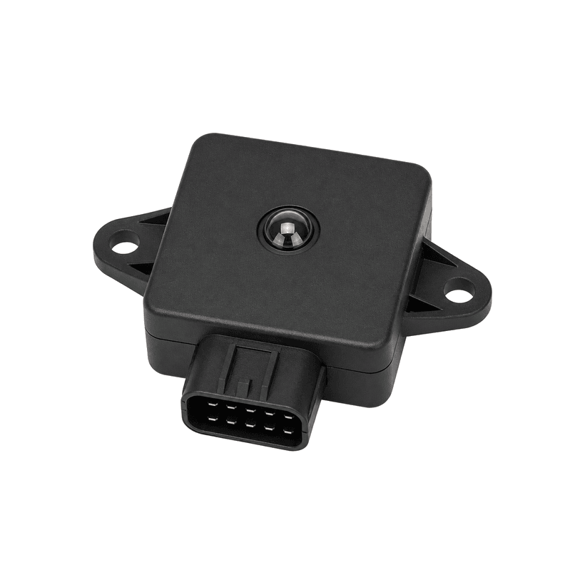
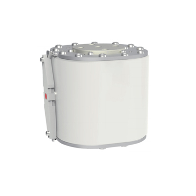
The YL02-WK belongs to the Switches & Sensors family as a discrete threshold input. It is about the simplest way to get a temperature fact into a circuit, and it pairs naturally with the parts that act on it: a body control module takes the contact as a digital input and decides what to do with it, while in a simpler build the contact drives a relay coil inside a power distribution box and the relay carries the fan. Where you need a measured value instead of a threshold, the CGQ-012A reads sun load and ambient temperature as an analogue input. For high-voltage pack protection on a new-energy build — a different kind of protective device entirely — see the JDK-2509 battery-pack fuse. The switch selector lists the family side by side, and the Switches & Sensors buyer guide covers how discrete inputs like this one reach the controllers that respond to them.
Build, testing and what gets fixed at RFQ
Built under IATF 16949 with APQP project planning and a PPAP package available for OEM programmes. End-of-line testing follows the programme's control plan — for a thermal switch that typically means verifying the actuation point and contact continuity — while sealing and life are validated on a sample basis in our in-house lab when a programme calls for fresh qualification. Because the whole specification lives in the part number, the actuation step, contact form, mounting style and lead length are all fixed on the release drawing at RFQ.
Questions we get on this series
Is this a temperature sensor? No. It is a switch with a fixed threshold — it reports crossed or not crossed, not a temperature. If you need a reading on the network you need a sender or an analogue sensor feeding a controller.
Is it automotive-only? No. Youlai lists the series for transformers, engines, integrated circuits and general electrical equipment. The engine application is what puts it on vehicles and machinery; the rest of the range is ordinary industrial and electrical use.
Which set point should I choose? Work backwards from the reset temperature, not the actuation temperature. Pick the step whose reset point is where you want the condition to clear, then check that the actuation tolerance still sits below whatever you are protecting.
Can it switch a fan directly? Only a very small one. The rating is 4 A at 12 V or 3 A at 24 V, which suits a relay coil, a lamp or a controller input. Anything larger should go through a relay or a power distribution output.
Does it need a supply? No. It is a passive dry contact with two non-polarised leads, so it works with whatever sensing scheme your circuit already uses.
Can I get a set point between the steps? The published series moves in 5 °C increments from 30 to 155 °C. Anything outside that grid is a programme enquiry rather than a catalogue selection — send the requirement and we will confirm whether it can be built.
How to ask
The YL02-WK belongs to the Switches & Sensors family. Tell us the actuation temperature you need and the reset point you can live with, whether the contact should be normally open or normally closed, how the probe will be fixed (M10 boss or strap), the lead length, the load the contact will switch, and the equipment it is going into — vehicle, transformer, cabinet or otherwise. We will confirm the full part number and the drawing. Use the contact page; drawings welcome.