
Connectors are the cheapest engineered parts in a vehicle electrical system and the ones that generate the most late-stage change requests. The pattern is familiar in a sourcing conversation: an enclosure is specified to IP67, a module is specified with a 24-pin connector, both parts are quoted and released, and then a question arrives that neither line answered — whether the wire seals are included, whether the part number quoted is the half on the module or the half on the loom, or why a module that passed validation is filling with water in a customer fleet.
This guide works through the attributes that decide those questions, using parts from our own catalogue as worked examples, not as a product list. Where the electrical system sits around these decisions — power, control, network and driver interface — is covered in the commercial vehicle E/E architecture guide; this one stays at the interface.
- The ingress class belongs to the mated pair, not to the enclosure. A sealed box with an unsealed connector face is an open box with extra steps. Where the rating lives
- Sealing is a chain of four interfaces — housing to housing, a wire seal per populated cavity, a plug in every unused cavity, and the seal where the joint passes through the enclosure wall. Omit one and the chain is open. What has to seal
- Mounting position picks the family before anything else does. Sealed families for the chassis, compact unsealed families for protected cab positions; these are two design worlds, not two points on a scale. Cab or chassis
- A part number does not announce which half it is. On one of our modules the harness-side housing and the module-side header are two different part numbers for the two ends of one joint. Which half is yours
- No connector family has a single current rating. Contact series, wire size, how many adjacent cavities are loaded and the ambient temperature all move it. What a contact can carry
The rating lives in the joint, not in the box
Start with the sentence that causes the most expensive surprises in this category, because it is stated plainly on our own quality pages and is still routinely designed around: an IP-rated enclosure with a non-sealed connector is not actually IP-rated. The ingress class describes an assembly in its installed state. Every opening in that assembly is part of it, and the largest deliberate opening in any electronic module is the connector face.
This is why sealed hardware in our range is specified around connector families, not around housings. The NBX‑971 waterproof central distribution box is IP67, and its standard build uses three sealed Deutsch harness-side connectors — two 12-pin DT06-12S bodies, black and grey, and one 18-pin HDP26-24-18PS — with the wire-side seals, terminal part numbers and pin-out confirmed against the customer harness drawing at quotation. The NBX‑961 sealed integrated box takes the same approach with a TYCO 1670901-series set, with other sealed families available per programme. In both cases the sealed connector is not an accessory to the IP67 claim; it is a load-bearing part of it.
The corollary is more useful than the rule. If a supplier quotes an IP67 enclosure without telling you which connector family it is built around, the rating has not yet been quoted — it has been asserted about a box. Our IP65 and IP67 protection page covers how the enclosure side is designed, from gasket grooves and controlled compression through to pressure equalisation; what the two digits themselves mean, and why automotive codes such as IP5K2 are not the same test as IEC 60529, is worked through in the IP ratings guide. This section is about the third thing: that the connector is where those two efforts either meet or fail to.
What actually has to seal
“Sealed connector” sounds like a part you can order. On a commercial vehicle it is four interfaces, and water finds whichever one was left out.
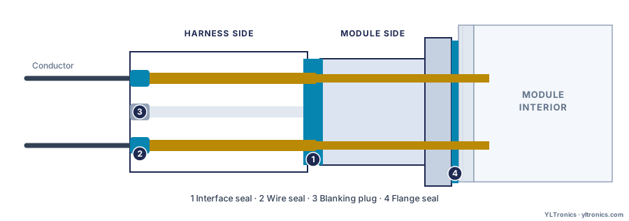
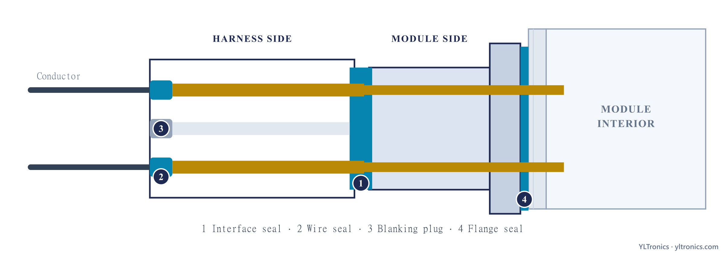
- The interface seal between the two housings. A silicone ring or face seal compressed when the pair is latched. This is the part everyone means by “sealed connector”, and it is the only one of the four that is normally quoted by default.
- A wire seal behind every populated cavity. Each conductor enters through its own small grommet. These are separate parts, sized to the insulation diameter of the wire, and a harness built with the right housing but the wrong wire seal is not sealed — which is exactly why the NBX-971 page states that wire-side seals and terminal part numbers are confirmed against the customer harness drawing, not assumed.
- A blanking plug in every unused cavity. Connectors are usually specified with spare ways for future options. An empty cavity in a sealed housing is a hole, and cavity plugs are the cheapest and most commonly forgotten item on the whole bill of materials. This one is easy to check in a catalogue: the TDK‑2408 travel pedal publishes a six-cavity DTM06-6S with four ways used — power, ground, CAN_H, CAN_L — and pins 5 and 6 declared unused. Two spare ways on a sealed housing is the normal case and not the exception, which is why the plug line belongs in the quotation.
- The seal where the joint passes through the enclosure wall. A module-mounted header is sealed to the wall by its own flange gasket or O-ring. Where a harness enters the housing directly instead of landing on a connector, the same job falls to a gland or bulkhead seal at the exit. Either way, this is the point at which the connector system hands over to the enclosure design, and it belongs to whoever owns the housing — which is why it is the one most easily assumed to be someone else's line item.
One consequence follows for how you buy, and it is the one that catches programmes late: when a supplier reports an ingress test, ask what state the sample was in. The result only describes what you will install if the mating connectors were fitted and the unused cavities plugged. The IP ratings guide covers how to word that as-shipped condition.
The families you will actually meet
These are the families on our published hardware, listed by job rather than by brand. Each row has a part you can open and check.
| Family | Character | Where it appears in our range |
|---|---|---|
| Deutsch DT / DTM | Sealed4–12 ways | EBX‑957 and EDK‑2507, both IP67 on a harness-side DT06-4S; TDK‑2408 travel pedal on a DTM06-6S.Both DT06-4S examples share the same CAN pin map — which half is yours. |
| Deutsch HD / HDP | SealedHigh density | NBX‑971 uses an 18-pin HDP26-24-18PS alongside its two DT06-12S bodies. |
| TE / AMP Multilock | UnsealedCompact, dense | EBX‑952 lands a 20-circuit harness on one Multilock at IP53; EBX‑954 uses six AMP / Tyco positions at IP54. |
| TE sealed multi-way | SealedColour-coded sets | EBX‑951, IP67: four TE sealed connectors — three 23-pin bodies in black, blue and natural plus one 8-pin, so the large housings cannot be swapped on the line. |
| TYCO 1670901 series | SealedBox-mounted sets | NBX‑961 sealed integrated box, IP67. Other sealed families available per programme. |
| Bussmann heavy-current | PowerBattery class | EBX‑2050 reserves two of its eight positions for Bussmann 32004-A2 and 32004-B2 battery inputs. |
| Molex, Sumitomo and platform-set families | MixedPlatform-led | TDK‑902/905 push-start pair: AMP 14-way and Molex 10-way. TDK‑2419 uses a Sumitomo housing; mating half and pinout confirmed per programme. |
If the plant already stocks the terminals, crimp tooling and repair kits, lock that family in the specification and say so. If it does not, fix the position and the circuits and let the supplier select within them.
Cab or chassis: the decision that picks the family
Sealed and unsealed are two design worlds, not two grades of the same part: different component counts, tooling, housing volume and behaviour in service. The mounting position picks which, not a preference for robustness.
Environmentally sealed families
Chassis rails, wheel arches, engine bays and machine bodies — road spray, standing water and dust are the duty, not accidents.
Compact unsealed families
Dashboards, behind trim, inside consoles — density and cost lead.
The EBX‑952 page states the trade-off instead of hiding it: power, ground, LIN, inputs and driver outputs share one connector, and a sealed-connector variant has to be specified at quotation if the programme needs chassis-mounted IP67. Same electronics; the mounting position picks the connector.
This also explains a pattern that confuses buyers comparing datasheets across suppliers. A module with a modest IP figure is not a lower-quality module. The EBX‑2050 power management unit is IP54 and carries twelve fuse positions, four relays and dozens of driver channels. Its published mounting guidance is to sit as close to the battery as the harness allows, so that the heavy-current run stays short, and its eight connector positions are allocated by current class, not sealed as one set. Reading that IP54 against an IP67 chassis box compares two different questions: one part is answering how to get battery-class copper into a fused distribution stage over the shortest possible cable, the other is answering what survives standing water on a rail.
One boundary is worth stating while the two worlds are side by side, because it is where sealed families are most often over-read. A sealed connector answers spray, dust and immersion. It does not by itself answer hot high-pressure washing, which is a separate duty with its own test method and its own temperature and pressure figures. If a fleet cleans its vehicles with a pressure washer or a steam lance, say so in the requirement rather than reading it into a sealed family name — the IP ratings guide sets out where that line falls and how to word it.
Which half you are ordering
A connector joint has two halves. A part number names one of them and does not say which. Three published modules show the shapes this takes:
| Module | The half you order | What it mates on the module |
|---|---|---|
| EBX‑952 | AMP 368511-1harness side | AMP 175785-1 PCB header. The two numbers are not interchangeable. |
| EBX‑2405 | TE 936098-1harness side, 26-way | TE 936133-2 |
| EBX‑2050 | Eight housingsharness side, by current class | None — the module-side faces are integral and have no separate part number. Confirm terminals and seals for the housings you do buy. |
In the Deutsch DT series, DT06 is a plug housing; DT06-4S is a four-cavity plug, and in our catalogue it is the harness-side half. The EBX‑957 and the EDK‑2507 both mate a harness-side DT06-4S on the same pin map — pin 1 supply, pin 2 ground, pin 3 CAN_L, pin 4 CAN_H. A sealed four-way is close to a default CAN-node interface on a commercial vehicle. They do not share an ingress class: the EBX‑957 is IP67, the EDK‑2507 is IP66. The connector sets the ceiling; the housing decides where under it the part lands.
Three habits prevent almost all of the errors here:
- Never quote a connector part number without naming the side in the same sentence. “Harness-side DT06-4S” is unambiguous; “DT06-4S connector” is not.
- Say who supplies which half. Normally the module carries its own face and you build the loom to it, but this is an assumption worth writing down rather than discovering at first sample.
- Ask for the terminal and seal part numbers separately. A housing part number does not specify the contacts inside it, and the contact is what carries your current.
Why one module carries several connectors
A recurring question in RFQ review is why a module has eight connectors instead of one, and whether the count can be reduced to simplify the harness. It usually cannot, because the positions are not an arbitrary division — they separate circuits that should not share a housing.
The EBX‑2050 is the clearest published example in our range. Its harness lands on eight connector positions allocated by current class: positions A and B take Bussmann 32004-A2 and 32004-B2 for the heavy-current battery inputs, positions C to F take AMP housings for signals, and positions G and H take AMP housings for medium-current actuator circuits. Battery-class copper, low-level signals and actuator drives want different contact sizes and different wire gauges, and keeping them in separate housings is what allows each to be terminated correctly.
Two further reasons apply even when the currents are similar. The first is buildability: several medium housings are easier to mate, route and strain-relieve than one very large one, and a high-way-count housing needs real insertion force once every cavity is loaded. The second is serviceability, and it is the one most often missed at design time — separate positions let a technician disconnect one subsystem without unplugging the vehicle. The EBX‑951 adds the error-proofing dimension: its four TE sealed connectors include three 23-pin bodies deliberately colour-coded black, blue and natural, so three otherwise identical housings cannot be crossed on the assembly line or in a workshop.
Keying does the same job mechanically. Where a platform carries several similar housings, the keys and colours are the defence against a harness being assembled into the wrong position — and they matter most exactly where the mistake would be invisible. Keying and colour frequently differ between the 12 V and 24 V versions of the same function for this reason, so that a 12 V panel cannot be fitted into a 24 V cab. What changes electrically on the other side of that split is covered in the 12 V vs 24 V guide.
What a contact can carry, and why no one publishes one number
“How many amps can this connector take?” is the most frequently asked question in the category and the one with the least satisfying answer: it depends on four things, none of which is the connector family name.
- The contact series and its plating. A housing family typically accepts more than one contact size. The contact, not the housing, carries the current.
- The conductor crimped into it. The terminal is sized to a range of cross-sections, and the wire is part of the thermal path. This is why connector part numbers in our catalogue are consistently accompanied by a note that terminals and wire gauge are confirmed against the customer harness drawing at quotation — the conductor is a customer input, not a supplier assumption.
- How many adjacent cavities are loaded. A fully populated housing runs hotter than the same contact carrying one circuit, because neighbouring contacts heat each other. Manufacturer derating curves are built around this, and it is the factor most often ignored in a quick calculation.
- The ambient temperature at the mounting position. The same connector behind a dashboard and on an engine-bay bracket are two different thermal problems.
The practical route around this is to specify the requirement rather than ask for the capability. Give a current figure and a conductor cross-section per circuit, plus the ambient temperature at the position, and let the supplier select the contact and confirm the derating. That is how our published hardware is organised: no per-pin figure anywhere in the catalogue, and current class published per position instead. Where a switched load is the point of the device and not a pass-through, the published figure belongs to the switch contact and not to the connector — the JDK‑2201 sealed toggle is rated 15 A at 24 V and 25 A at 12 V, and it lands that circuit on a TE 282105-1 interface. The connector has to carry the current; it is not what defines it.
One question worth asking explicitly when a joint carries real current: what is the expected number of mating cycles, and is this a connector a technician will open in the field? Contact plating wears with mating, and a joint designed for ten factory cycles behaves differently from one a workshop opens every service interval. It costs nothing to state at RFQ and is difficult to retrofit.
Writing a connector line a supplier can quote
Six inputs make a connector line quotable. Missing any of them, the quote waits on your harness drawing — after the rest of the design has hardened around it.
Connector requirement
- Mounting position and required ingress class at the connector facee.g. chassis rail, IP67 with mating connectors fitted
- Family constraint, if anyfixed to an existing plant standard, or open to supplier selection
- Circuit list with current and conductor size per circuitnot a pin count alone; note battery-class feeds separately
- Which half each party suppliese.g. module carries its face; harness side built to loom drawing xxx
- Keying, colour and cavity pluggingwhere a vehicle carries several similar housings
- Service expectationmating cycles, and whether the joint is opened in the field
Sealed positions: confirm that wire seals sized to your conductors and plugs for unused cavities are included in the quotation, not assumed.
The connector is usually specified last, after the electronics and the enclosure. That order is backwards: sealed against unsealed changes the housing and its validation, and the number of positions changes the vehicle harness. Both are cheap at RFQ and expensive at first sample. The RFQ checklist puts this line with the other quotation inputs; the OEM sourcing guide covers IATF 16949, APQP and PPAP once a programme is running.
If you already know the mounting position and the circuit list, that is enough to start.