
Almost every voltage argument we see in a sourcing conversation starts the same way. The specification said 24 V. The parts were quoted against it, the harness was drawn, and then someone asked a reasonable follow-up question — what happens during cranking, or where the 12 V feed for the refrigerator comes from, or whether the relay carried over from the last programme is still good for its printed rating. Each answer turns out to depend on something the two-character line never said.
The nominal figure is a label for a family of decisions rather than a decision in itself, and this guide works through the ones that cost money. How the layers of a vehicle's electrical architecture fit together — power, control, network, human interface — is covered in our commercial vehicle E/E architecture guide; this one stays on the voltage axis.
- 24 V halves the current, not the power. Half the current is a quarter of the heat in the same copper, and that is the whole case for it. Why 24 V won
- Specify a range, never a nominal. 9–16 VDC and 18–32 VDC are the usual windows, with cranking, jump-start and transients as three further numbers on top. What a module must survive
- Contacts derate as voltage rises. One of our sealed toggles carries 25 A on a 12 V system but 15 A on a 24 V one, same contact set, because a DC arc does not self-extinguish. Contact derating
- Never tap the battery midpoint for 12 V. Step down across the full 24 V bus instead — an equaliser for heavy loads, an isolated converter where the ground reference has to be separated. Building a 12 V branch
- On an electric platform the auxiliary voltage is decided separately from the driveline. Ask for it; it cannot be inferred from the powertrain. Electric platforms
Why heavy vehicles settled on 24 V
The whole question rests on one piece of arithmetic, and it is worth doing explicitly because the consequence is not linear. Power is voltage times current, so a given load at 24 V draws half the current it would at 12 V. Voltage drop along a cable is current times resistance, so that too halves. But the power wasted as heat in the cable follows the square of the current, so it falls to a quarter.
A 2.4 kW load at the end of a 5 m copper feed
This is what sets terminal and fuse class.
Halves in volts; relative drop falls from 5.7 % to 1.4 %.
A quarter — heat follows current squared.
25 mm² copper, chassis return, 20 °CA two-wire return doubles drop and loss; resistance rises about 0.4 % per °C. The ratios are the point.
Now apply that to a vehicle rather than a cable. A heavy diesel starter is somewhere in the 4 to 7 kW class; at 12 V that is a peak draw in the region of 500 A, at 24 V nearer 250 A. Cranking is also the moment when voltage drop matters most, because the starter is trying to turn a cold engine while the battery terminal voltage is already sagging. Every tenth of a volt lost in the cable is torque that never reaches the flywheel.
Then add length. A tractor unit runs its feed several metres from the battery box to the cab and further again to the rear of the chassis, and articulated combinations extend the same problem across the trailer coupling. Copper sized for 500 A over that distance is heavy, expensive, difficult to route around a frame rail and awkward to terminate. At half the current the same job is done with a smaller cross-section, a lighter harness and a cheaper set of terminals. That is the whole case for 24 V, and it is an economic one rather than a performance one.
It also explains why the split falls where it does. A passenger car has a smaller starter, a shorter harness and enormous production volumes that reward the cheaper 12 V component ecosystem. It never accumulates enough copper for the arithmetic to turn. A 40-tonne truck does, in the first metre.
The number on the drawing is not the number the part must survive
A 24 V vehicle spends very little of its life at 24 V. A charging system holds the bus meaningfully above nominal, cranking pulls it down hard for a second or two, and a workshop jump-start can push it higher still. So the figure that belongs against a module is a range. The windows below are the ones most commonly written against the two nominal systems, and the ones our own parts are specified to:
| Nominal | Continuous range | Where it appears in our range |
|---|---|---|
| 12 V | 9–16 VDC | TDK‑2202/3 door and window switch set, EBX‑2305 body control module, EBX‑2301 network gatewayPassenger, light commercial and battery-electric platforms |
| 24 V | 18–32 VDC | EBX‑954 heavy-truck BCM, EDK‑907 CAN switch panel, PBX‑961 windscreen HUDHeavy truck, bus and most construction machinery |
| Either | 8–36 VDCVaries by part | EBX‑2054 telematics box at 10–32 VDC, PBX‑2203 combiner HUD at 9–32 VDCWide-input parts — see one part number, both systems |
| Traction | 400–750 VDC | EBX‑2314 DC-DC controller input, JDK‑2509 pack-side fuseA separate domain — see electric platforms. The fuse's DC 1500 V figure is a device withstand rating, not a system operating range. |
Both low-voltage windows are the same proportion of their nominal, roughly three quarters to a third above, which is why 18–32 VDC is exactly double 9–16 VDC. That symmetry is a useful sanity check when you read a datasheet: a 24 V part quoted at, say, 20–28 VDC has a narrower window than the convention, and it is worth asking what the input stage does outside it. These are conventions rather than a mandated pair of figures, though, and individual OEM specifications do vary — which is exactly why the range belongs in the requirement instead of being assumed from the nominal.
Continuous range is only the first of four voltage conditions, though, and the other three are the ones left out of most RFQs:
- Cranking dip. How far the bus falls and for how long. A module that resets during cranking is a warranty problem even though nothing failed.
- Jump-start. A voltage above the continuous ceiling, held for minutes rather than milliseconds, applied by someone in a hurry. It is a survival requirement, not an operating one.
- Conducted transients. Load dump and switching disturbances on the supply line, tested to ISO 7637-2, alongside the electrical-load tests of ISO 16750-2 and, for the Chinese market, QC/T 413. Our EBX‑2315 window and mirror controller carries QC/T 413, ISO 16750-1 and ISO 7637 on its compliance line, and the EDK‑907 panel carries input over-voltage protection across its whole 18–32 VDC range for exactly these events.
The reason to separate them is that they are separate tests, and passing one says nothing about another. A part qualified to operate at 32 V continuously has not thereby been shown to survive a jump-start at 32 V for a minute, and neither result describes what happens when the alternator load dumps. Ask for them individually, and expect a supplier to answer them individually. Validation of this kind is what our in-house EMC and environmental laboratory exists for; certified testing goes to third-party accredited laboratories when a programme requires it.
Which platforms run which
The convention is stable enough to plan around, with one important exception at the bottom of the table.
| Platform | Typical system | What drives it |
|---|---|---|
| Passenger car, van, light commercial | 12 V | Modest starter, short harness, and the cheapest component ecosystem by volume. |
| Heavy truck, tractor unit | 24 V | Large starter current and long cable runs; the copper saving is decisive. |
| Bus and coach | 24 V | Vehicle length plus a heavy continuous auxiliary load, HVAC above all. |
| Construction and agricultural machinery | 24 V12 V on compact classes | Follows engine size. Compact machines often stay 12 V, so machinery parts are frequently specified wide — the TDK‑2408 travel pedal covers 8–32 VDC for this reason. |
| Battery-electric commercial vehicle | Either | Decided by the body electrical system, not the driveline. Confirm it explicitly — see electric platforms. |
That last row causes more sourcing confusion than the rest of the table combined. When a programme is described to us only as “electric”, the auxiliary bus voltage is the first thing we ask about — the traction pack has no bearing on it, and the section on electric platforms works through why.
One more confusion is worth pre-empting: voltage class is not a proxy for quality or capability. A 12 V module is not a lighter-duty part than its 24 V sibling. Our EBX‑2313 BCM platform is offered in either class, confirmed per programme, and the difference sits in the input stage and the drive outputs rather than the standard of the build.
A contact rated for 12 V is not the same contact at 24 V
This is one of the most common carry-over errors, and it is easy to make because the failure is slow. A relay or switch is reused from a 12 V programme on the strength of its printed current rating, works perfectly in validation, and then starts returning from the field a year later with welded or eroded contacts.
The physics is about breaking the circuit rather than carrying it. When contacts separate under load, an arc forms across the opening gap. On alternating current that arc extinguishes naturally every time the waveform crosses zero. Direct current never crosses zero, so the arc has to be stretched and cooled until it can no longer sustain itself — and the higher the system voltage, the longer it sustains and the more energy it deposits on the contact face. The same contact set therefore carries a lower rating at 24 V than at 12 V.
Our own catalogue states this plainly rather than leaving it to be inferred. The JDK‑2201 sealed toggle is published at 25 A on a 12 V system and 15 A on a 24 V system — one switch, one contact set, and a rating that falls by 40 % when the system voltage doubles. The same pattern holds on a far smaller contact: the YL02‑WK thermal switch is 4 A at 12 V and 3 A at 24 V. A datasheet that prints one current figure with no voltage attached is usually quoting a carry rating rather than a switching one — worth asking about rather than assuming, because they are different questions.
Inductive loads sharpen the effect. A relay coil, a motor or a solenoid stores energy in its magnetic field, and at the moment of break that energy appears as a reverse voltage spike that helps sustain the arc. Three practical consequences follow:
- Read the rating at your system voltage, and if only one figure is printed, ask which voltage and which load category it was measured under. A resistive rating does not transfer to an inductive load.
- Put the suppression on your side of the interface — a flyback diode across a DC coil, or an RC snubber. It costs almost nothing and it is one of the cheapest ways to buy contact life.
- Switch the coil, not the load, wherever the current is significant. Let a relay or a driver stage in a power distribution box carry the current, and use the switch only to command it. This is also how the circuit's status reaches the vehicle network instead of staying a local wire.
The same logic applies to fusing. Halving the current does not simply halve the fuse rating, because the fuse still has to coordinate with inrush, with the conductor it protects and with the ambient temperature it sits in. Distribution hardware is normally specified across a wide window for this reason — the NBX‑980 main-feed module works from 9 to 36 VDC and takes bolt-down MEGA and MIDI fuses in the 30–200 A class, with the values inside chosen per circuit rather than per system voltage. One figure worth asking for explicitly is the fuse's DC breaking capacity at your system voltage, since interrupting direct current is harder than the alternating-current case most fuse tables grew up around. Which style of distribution box a given job needs is worked through in relay box vs fuse box vs junction box.
Running a 12 V branch on a 24 V vehicle
Most 24 V vehicles end up needing some 12 V somewhere. A cab refrigerator, a radio, a telematics accessory, a body-builder fitment, or a part that simply only exists in a 12 V version because it came from the passenger-car world. The question is not whether you will need it, but how you will build it.
The wrong answer is a midpoint tap, and it is worth being blunt about why, because it looks so reasonable. On a conventional diesel truck a 24 V system is built as two 12 V batteries in series. The midpoint between them sits at 12 V relative to chassis ground, so a wire there does deliver a working 12 V supply, and it costs nothing.
What it also does is draw exclusively from the lower battery while the alternator charges the two as a single string. The tapped battery is discharged harder than its partner and never brought back to the same state of charge, so the pair drifts apart. From there it compounds: the weaker battery is worked harder every cycle, ages faster, and drags the string down. The usual outcome is a stack that reaches replacement considerably sooner than a balanced pair would, and because batteries are replaced in matched sets, the bill is for both. Vehicles come back with the symptom recorded as a battery problem, and the wiring that caused it is rarely the first thing anyone looks at.
Not every 24 V vehicle is built from a series pair — some platforms use a single 24 V pack, and on an electric vehicle the low-voltage bus is produced by a converter rather than a battery string at all. The midpoint problem belongs specifically to the series-pair arrangement. It is worth knowing because that arrangement is what most 24 V diesel vehicles use, and because the habit of tapping it travels between programmes.
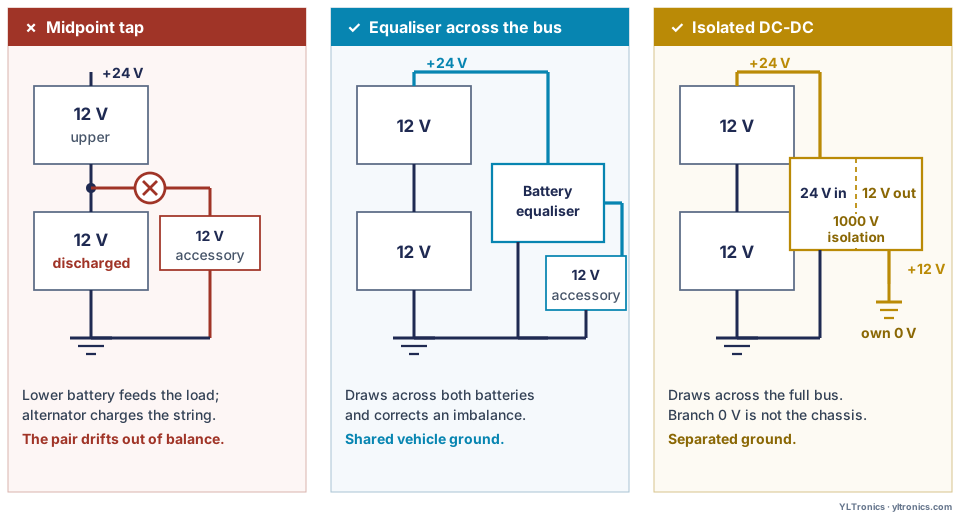
Two routes do it properly, and choosing between them is a real engineering decision rather than a formality.
Battery equaliser
24 V to 12 V for a heavy load, and it actively rebalances the stack.
- EBX‑2407 — 16–32 VDC in, 100 A or 30 A SKU
- CAN diagnostics: over-voltage, under-voltage, output low, over-temperature with derate
- M8 studs for ring-terminal cables
- IP67 + IP66K finned aluminium, chassis-side
Isolated DC-DC converter
A 12 V rail with its own 0 V, galvanically separated from the vehicle ground.
- EBX‑2515 — 9–36 VDC in, 12 V / 15 A / 180 W out
- 1000 VDC primary-to-secondary isolation
- 91.5 % efficient from 24 V; 17 A current limit
- IP67 potted aluminium
Four questions usually settle it: how much current the branch draws continuously and at peak, whether the sub-system needs its ground reference separated from the vehicle chassis, how much output ripple the load can live with, and whether the existing stack has already drifted out of balance.
Heavy loads — a fridge, a lift, an inverter, anything in the tens of amps — point to the equaliser, and the 100 A SKU exists for exactly that. A sub-system that has to sit on its own reference points to the isolated converter, and the 1000 V barrier is the whole reason to choose it. Worth separating two properties that often get conflated there: isolation is not the same thing as a quiet supply. The EBX‑2515 breaks the ground loop, but its output ripple is specified at 1600 mVp-p from a 24 V input, so a precision analogue front end still needs its own ripple budget checked and, usually, local filtering behind the converter. On the balance question, both routes remove the cause simply by drawing across the full bus — but where a legacy tap has already pulled the stack apart, the equaliser is the one that actively corrects the imbalance rather than merely stopping it from growing.
Either route also lands on the distribution layer, because a vehicle running two voltages now has two main feeds to protect close to the battery. That is a specification detail worth catching early: our NBX‑980 main-feed module carries two independent input studs for exactly this case — M8 for the 24 V battery cable, M6 for the 12 V one — so both feeds are fused at the first point downstream of the battery instead of one of them being picked up somewhere further along the harness.
One thing neither route removes is the need to declare the branch. A 12 V sub-system on a 24 V vehicle changes the load list, the fusing plan and the quiescent-current budget, and it should appear in the specification as its own item with its own continuous and peak current. It is one of the most common omissions we see in an otherwise complete RFQ.
When one part number covers both systems
Some functions do not care much about supply voltage, and for those a wide input window lets a single part number serve a mixed fleet. The gains are real: fewer part numbers, simpler spares, one qualification cycle, and one less opportunity for the wrong variant to reach the wrong vehicle.
| Part | Input range | Function |
|---|---|---|
| EBX‑2054 | 10–32 VDC | Telematics box, dual-rated for 12 V and 24 V on one hardware platform |
| TDK‑2408 | 8–32 VDC | Bidirectional travel pedal, input withstands at least 50 VDC |
| PBX‑2203 | 9–32 VDC | Combiner HUD — the wide window removes the need for a 12 V / 24 V variant pair |
The trade-off is real and worth stating, because “wide input” is sometimes read as strictly better. An input stage optimised across a 9–36 V window cannot be optimal at both ends. The EBX‑2515 above is a clean illustration: it converts at 91.5 % efficiency from a 24 V input but 83.3 % from 12 V, because the same topology is working much harder at the bottom of its range. On a part drawing a few watts that is irrelevant; on a continuous load it is heat you have to get rid of.
A wide input range also does not exempt a part from transient testing at each nominal voltage it will actually see — the ranges overlap, the disturbance levels do not. Nor does it say anything about the output side. The JDK‑2201 makes that point in a single part: it operates anywhere across 9–32 VDC, and its contacts are still rated 25 A at 12 V and 15 A at 24 V, because the supply window and the switching duty are two different questions. A driver module sized for 12 V lamps is not made suitable for 24 V ones by widening its input either. Standardise where the function is genuinely voltage-tolerant, and accept separate part numbers where drive current or contact rating is the point of the device. The switches and sensors selector filters the range by supply voltage directly, including the wide-range parts.
Where voltage sits on an electric platform
An electric commercial vehicle carries more than one voltage domain — at least two, often three — and confusing them is the source of most specification errors on these programmes.
The traction pack is a high-voltage domain, commonly in the 400–750 VDC class. The low-voltage auxiliary bus is the 12 V or 24 V system everything in this guide has been about — lights, controls, cab electronics, body functions. And where that bus is 24 V, there may be a further 12 V branch off it, built as described above.
The low-voltage side never draws from the pack directly. A DC-DC stage stands between them and becomes, in effect, the vehicle's alternator: our EBX‑2314 takes 600 VDC nominal over a 400–750 VDC range and produces the 24 V auxiliary bus at 36 kW rated and 40 kW peak, at 95 % full-load efficiency and with on-board pre-charge control. It also reserves a 10 kW high-voltage output for HV-side accessories such as heaters and compressors — loads that never appear on the low-voltage list at all, and are therefore the ones most often missed when a load budget is assembled. Pack-side protection is a separate discipline again, handled by components such as the JDK‑2509 at DC 1500 V in the aBat category of IEC 60269-7.
Three things follow for sourcing. State every range separately in the specification, because qualification against one says nothing about the others. Treat the auxiliary bus voltage as a declared design choice rather than something to infer from the driveline — ask for it. And give the DC-DC stage the attention its position earns: it is the sole source for the entire low-voltage system, so its continuous rating, its thermal derating and its behaviour on fault matter as much as the headline power figure. Whether that amounts to a single point of failure depends on the architecture — an auxiliary battery, a redundant converter or a defined limp-home strategy each change the answer, and it is worth asking which of them the platform assumes. Our electric commercial vehicle overview walks the whole low-voltage stack by system.
What changes when a platform moves from 12 V to 24 V
Programmes carry architectures across, and the voltage change is often treated as a parts substitution. It is closer to a re-specification of everything that touches power. Working checklist:
- Every module's operating window moves, 9–16 VDC to 18–32 VDC. This is a re-qualification, not a relabel.
- Currents halve, so conductors and fuses all shift — but not by simply halving the numbers. Re-run the voltage drop over the actual routed length, and re-check fuse coordination against inrush and worst-case ambient.
- Contact and relay ratings must be re-read, per the derating above. This is the item most often missed.
- Motors, lamps and heaters are different parts, not the same parts on a different supply. A 12 V motor is not a 24 V motor at half the current.
- Connector pinouts and keying frequently differ between the voltage classes of the same function, which is deliberate — it prevents cross-fitment. How to write that interface into a specification — sealed against unsealed, which half you are ordering, and what a sealed set has to contain — is covered in the automotive connector guide.
- EMC and transient validation is repeated, because the disturbance levels are defined per nominal voltage.
- The network layer often carries across. CAN and LIN transceivers run from a regulated internal rail, so the message set, the baud rates and the diagnostic layer generally survive the change intact. This is the part of the architecture worth deliberately protecting during a migration, and it is why the interface choice should be made on its own merits rather than as a consequence of the voltage decision.
Door and cab controls are a good worked example of how this lands in practice, because the same function exists in both worlds with different parts: the TDK‑2202/3 set is the 12 V design at 9–16 VDC, while the EDK‑908 and EDK‑914 cover the 24 V cab at 18–32 VDC. Our door and window switch panel guide compares them directly.
Writing the voltage requirement into a specification
The aim is a line a supplier can quote without a follow-up call. Nine items cover it:
- Nominal system voltage — 12 V or 24 V, stated rather than implied by vehicle type.
- Continuous operating range the part must hold, in volts.
- Inrush and peak current — what the part draws at switch-on and at worst case, not only its steady figure. Fuse coordination is built against these rather than the average.
- Cranking dip — minimum voltage and duration, with whether the part must keep operating or may reset and recover.
- Jump-start — voltage and duration to be survived.
- Conducted transients — standard and level, typically ISO 7637-2 alongside the electrical-load conditions of ISO 16750-2.
- Reverse-battery protection — required or not, and whether on the main input only or every channel.
- Quiescent current budget at KEY OFF, which is what drains a parked vehicle over a weekend.
- Any 12 V branch on a 24 V vehicle — its continuous and peak current, and whether isolation is required.
Written out, that is one paragraph. The shape of it, with figures that are illustrative only — the actual levels belong to the OEM programme and the standards it calls up: 24 V nominal; continuous operation 18–32 VDC; must ride through a cranking dip to 10 V for 1 s without reset; survive a jump-start at 36 V for 60 s; conducted transients per ISO 7637-2 at the levels in the attached programme sheet; reverse-battery protection on the main input; quiescent current below 3 mA at KEY OFF; separate isolated 12 V branch, 8 A continuous. Note that the jump-start figure sits deliberately above the continuous ceiling — it is a survival condition, not an operating one, and quoting the same number for both is a common way to leave a real requirement unstated. Every figure there is a decision someone has to make eventually. Making them at RFQ stage costs an hour; making them after tooling costs a change request.
If you want the rest of the sourcing package around that line — application, environmental, programme and volume detail — our RFQ checklist sets out what a supplier needs to quote accurately, and the IP ratings guide covers the sealing line that usually sits next to it on the same page.